
Check the circuit diagram of a three-phase motor with broken bars
The inspection circuit for a three-phase motor with broken bars is designed to diagnose and evaluate the condition of the motor's rotor. Broken bars in an induction motor can lead to significant performance issues, including reduced efficiency, increased heat generation, and potential motor failure. The schematic typically includes key components such as current transformers, voltage sensors, and a microcontroller to analyze the data collected.
The circuit begins with the three-phase supply connected to the motor. Each phase line is monitored by current transformers that provide real-time current measurements. These measurements are essential for identifying imbalances that may indicate broken rotor bars. The output from the current transformers is fed into an analog-to-digital converter (ADC) within the microcontroller.
The microcontroller processes the current data and compares it to predefined thresholds. If an anomaly is detected, such as significant current differences between phases, it triggers an alert signal. This alert can be visualized on an LCD display or sent to a remote monitoring system for further analysis.
In addition to current monitoring, voltage sensors are integrated into the circuit to assess the supply voltage levels. Maintaining proper voltage levels is crucial for the motor's operation, and deviations can further exacerbate issues related to broken bars.
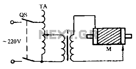
The inspection circuit may also include protective elements such as fuses or circuit breakers to prevent damage from overcurrent situations. Overall, this inspection circuit serves as a vital tool for maintenance personnel to ensure the longevity and reliability of three-phase motors, enabling timely interventions before catastrophic failures occur. Check the three-phase motor with broken bars As shown in the three-phase motor with broken bars of inspection circuit:
Related Circuits
Do not forget to seal your wire splices with heat shrink tubing. It provides tensile strength to wires, is flame-retardant, and protects against fraying. Heat shrink tubing forms a protective, insulated, water-resistant covering over wiring splices, crimp terminals, and...

This is a simple ultrasonic mosquito repeller circuit diagram. The circuit is designed based on the theory that pests like mosquitoes can be repelled by ultrasonic frequencies ranging from 20 kHz to 25 kHz. This ultrasonic mosquito repeller circuit...

This circuit is a melody generator circuit diagram controlled by the UM66 IC. The UM66 is a CMOS IC designed for applications such as call bells, telephones, and toys. It features a built-in ROM programmed to play music and...

While developing an infrared (IR) extender circuit, a method was needed to measure the relative intensities of different infrared light sources. This circuit utilizes an SFH2030 photodiode as the infrared sensor. A CA3140 MOSFET operational amplifier is employed in...

A simple tool to check the degree of radiation from an electric or electronic instrument. The LEDs in the circuit will provide a running light pattern when the circuit detects electromagnetic radiation from the device. It can identify radiation...

This tremolo effect circuit utilizes the XR2206 and TCA730 integrated circuits, designed for electronic balance and volume regulation with frequency correction. The circuit is beneficial for stereo channels and can simulate the Lesley effect, also known as the rotating...