
Ultrasonic Mosquito RepellerCircuit by CD4017
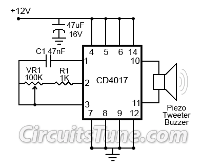
The ultrasonic mosquito repeller circuit operates on the principle that certain high-frequency sounds, inaudible to humans, can deter mosquitoes and other pests. The core of the circuit is the CD4017, a decade counter that functions as a frequency generator when configured appropriately. The output frequency is crucial for the effectiveness of the device; thus, it is adjustable through the combination of capacitor C1 and resistor R1, along with the variable resistor VR1.
In this configuration, C1 determines the timing characteristics of the oscillation, while R1 and VR1 allow for fine-tuning of the frequency output. By altering the resistance, the time constant of the RC network changes, thereby modifying the frequency of the generated ultrasonic sound. The desired frequency range of 20 kHz to 25 kHz is pivotal, as this range has been identified as effective for repelling mosquitoes.
The circuit typically includes a power supply section that provides the necessary voltage to the CD4017, ensuring stable operation. An output stage, which may consist of a small speaker or piezoelectric transducer, converts the electrical signals into ultrasonic sound waves. Proper layout and component selection are essential to minimize interference and ensure that the ultrasonic waves are emitted efficiently.
Overall, this circuit represents an innovative approach to pest control, leveraging the properties of ultrasonic sound to create an environment less hospitable to mosquitoes without the use of chemicals or traps.This is a simple ultrasonic mosquito repeller circuit diagram. The circuit is design on the theory that pests like mosquito can be repelled by ultrasonic frequency around (20KHz-25KHz). This ultrasonic mosquito repeller circuit is based on a single CMOS IC CD4017. C1, R1 & VR1 is used to adjust the output frequency. 🔗 External reference
Related Circuits
The MC33411 900 MHz Analog Cordless Phone Baseband system is designed to meet the specifications of a 900 MHz Analog cordless telephone system. It includes three Phase-Locked Loops (PLLs). Two of these PLLs are intended for use with external...
Ultrasonic cleaning primarily relies on the phenomenon of ultrasonic cavitation. In the presence of a sound field, liquid bubbles undergo high-frequency micro-vibrations. When the sound pressure reaches a specific threshold, air bubbles grow rapidly and then collapse suddenly, creating...
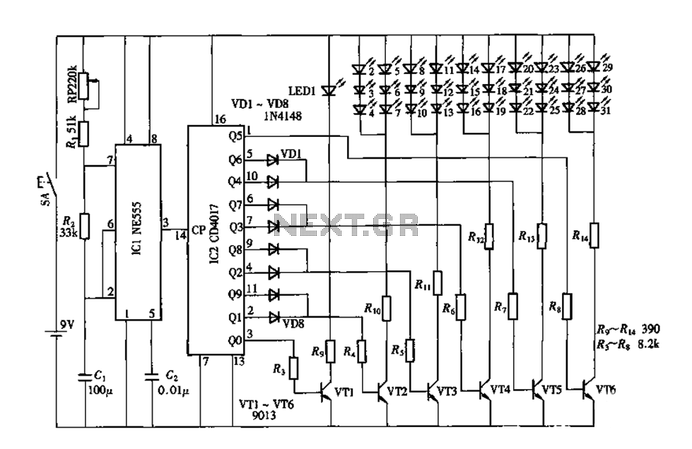
An electronic decorative peacock consists of 10 light-emitting diodes (LEDs), each of which contains multiple LEDs arranged in the tail of the peacock model. The light emission drive circuit operates the fan-shaped LEDs in a cyclic manner, emitting light...
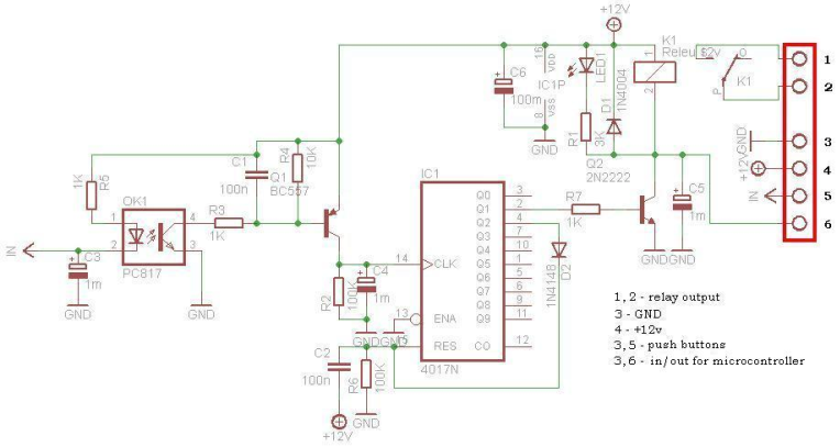
This circuit is operating the room illuminates. The basic component of the circuit is a IC1 (CD4017). Push buttons room are connected by normally wired to the circuit. All circuit is separately by optocoupler, which means that the circuit...
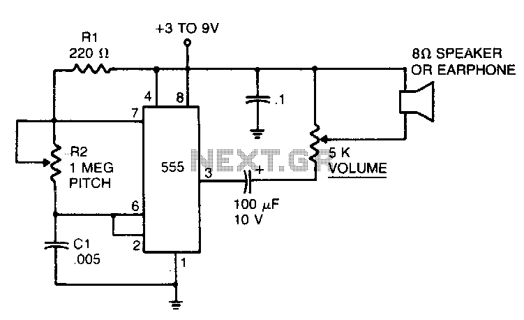
In the 555 oscillator circuit, adjusting R2 will provide output frequencies ranging from below 200 Hz to above 62 kHz. It is recommended to use a good quality miniature speaker to produce frequencies around 20 kHz. The 555 oscillator circuit...
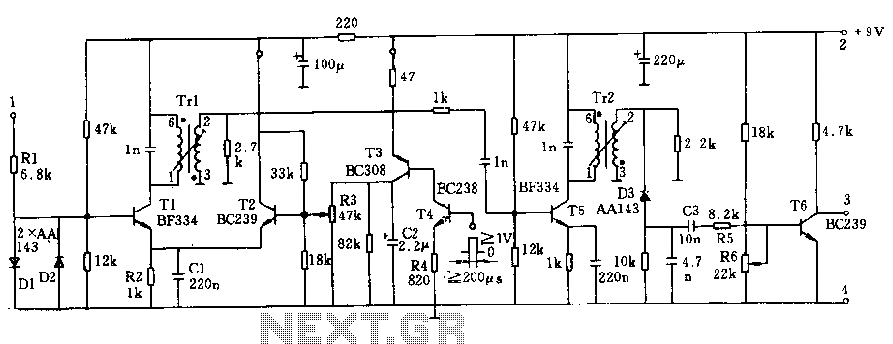
The circuit operates at a voltage of 9V with a current consumption of only 5mA. It allows for frequency adjustment within the range of 150 to 180 kHz, featuring a bandwidth of approximately 20 kHz. This configuration ensures that...