
Check the three-phase motor with broken bars
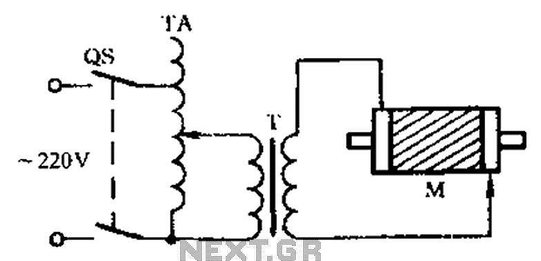
The circuit for a three-phase motor with a broken bar inspection system typically consists of several key components that work together to monitor the health of the motor's rotor. The inspection circuit is crucial for identifying faults that could lead to reduced efficiency or catastrophic failure.
In this setup, the three-phase motor is powered by a three-phase supply, which provides the necessary torque and speed for operation. The inspection circuit includes current sensors placed in each phase line to monitor the current flowing through the motor. These sensors can be Hall effect sensors or current transformers, which provide real-time feedback on the electrical conditions of the motor.
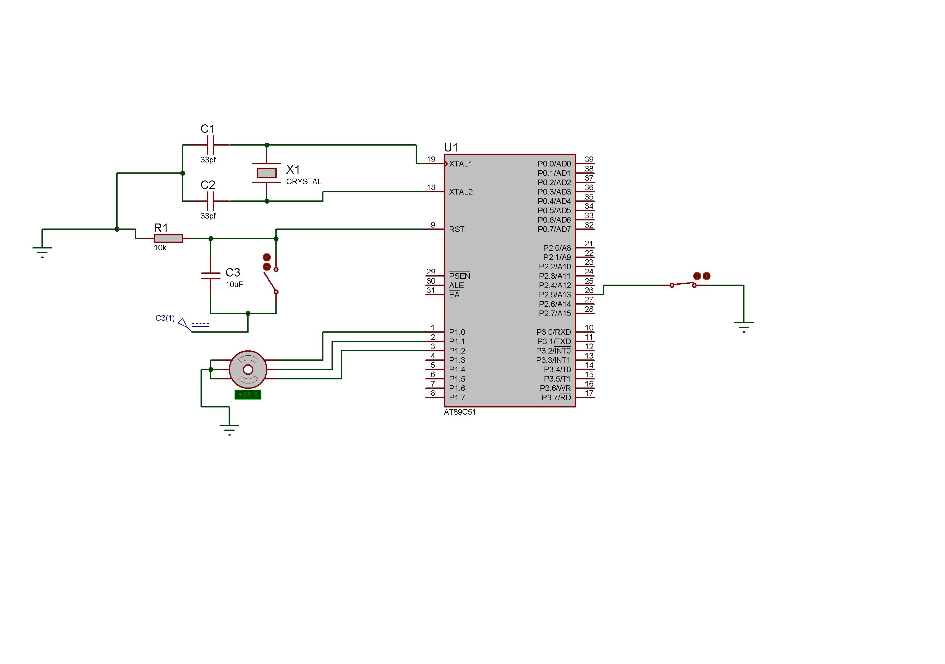
The output from the current sensors is fed into a microcontroller or a dedicated monitoring unit. This unit processes the signals and compares the current readings against predefined thresholds. If the current in any phase deviates significantly from the expected value, it may indicate a broken bar in the rotor. The microcontroller can then trigger an alarm or an indicator light to alert maintenance personnel of the potential issue.
Additional components in the circuit may include resistors for signal conditioning, capacitors for noise filtering, and possibly an interface for communication with a supervisory control and data acquisition (SCADA) system. The design must ensure that the inspection circuit is robust enough to operate under the motor's environmental conditions, which may include vibrations and temperature fluctuations.
In summary, the three-phase motor with a broken bar inspection circuit is an essential system for ensuring reliable motor operation, minimizing downtime, and enhancing overall maintenance practices. As shown in the three-phase motor with broken bars of inspection circuit:
Related Circuits
Stepper motors consist of a permanent magnet rotating shaft, known as the rotor, and electromagnets on the stationary part that surrounds the motor, referred to as the stator. One complete rotation of a stepper motor is illustrated. At position...
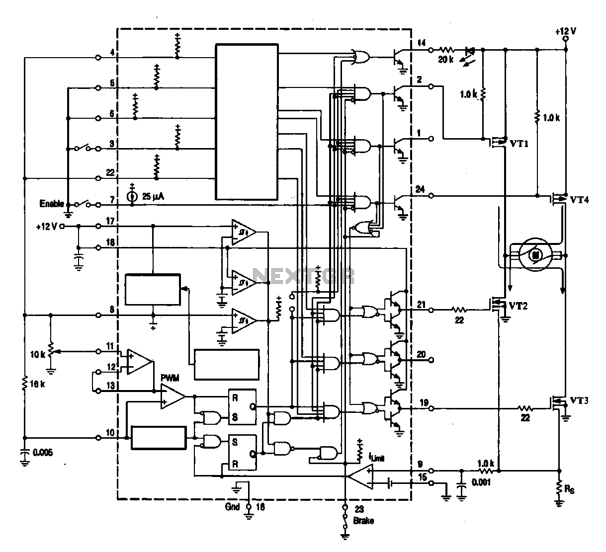
A DC brush motor driver circuit diagram utilizing the MC33035 chip is presented, illustrating a typical configuration for driving a straight DC brush motor. The circuit incorporates a field-effect transistor (FET) bridge driver setup. When transistor VT3 is activated,...
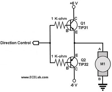
The following circuit illustrates a two-transistor DC motor driver circuit diagram. This circuit utilizes the TIP32 transistor. Features: operates in... The two-transistor DC motor driver circuit is designed to control the operation of a DC motor using two NPN transistors,...
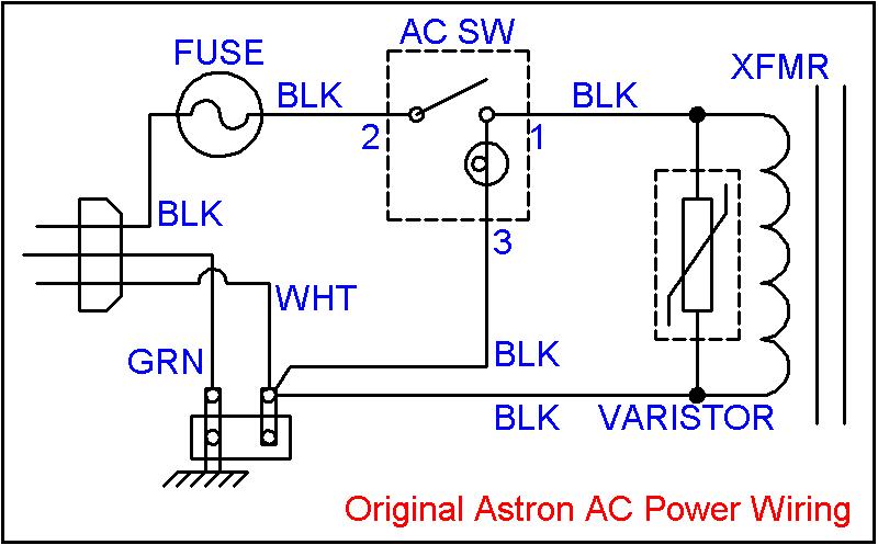
The regulated output voltage fluctuated as the unregulated DC voltage changed, which in turn varied with the load current or the incoming AC line voltage. There was no straightforward solution to the existing circuit that would rectify this issue....
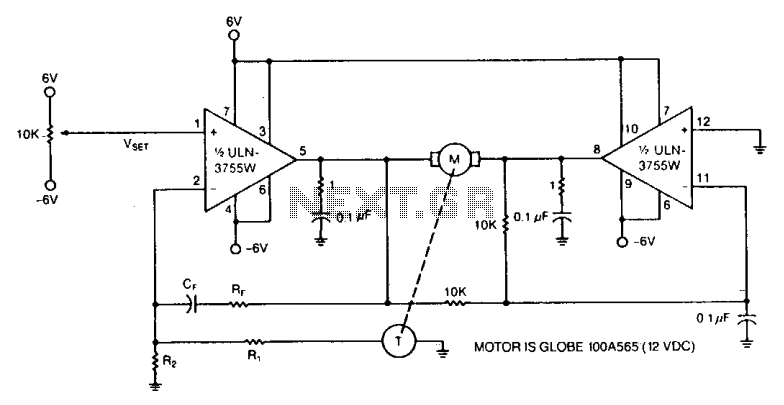
Power operational amplifiers provide precise speed control for DC motors. The circuit enables bidirectional speed control. The push-pull configuration of the amplifiers ensures a full rail-to-rail voltage swing (minus the saturation drops of the output stages) across the motor...
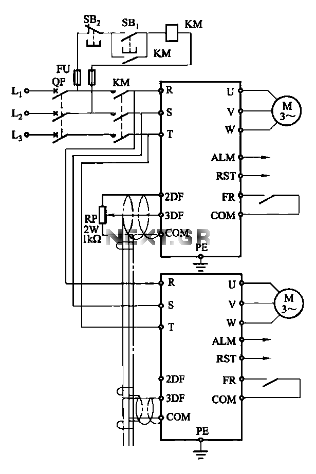
Each motor operates with an independent drive; however, only one frequency is utilized for a specific device. This setup employs a single RP potentiometer to control multiple motors in parallel. In this configuration, the circuit design allows for multiple motors to...