
Chevrolet Malibu 1997 Electrical Wiring Diagram
The electrical wiring diagram for the 1997 Chevrolet Malibu is a crucial resource for understanding the vehicle's electrical system. This diagram provides a detailed representation of the wiring layout, illustrating connections between various electrical components and systems within the vehicle.
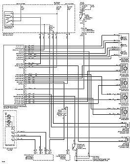
Key features of the diagram include the performance circuits associated with the 2.4L engine (VIN T), which encompass critical elements such as the ignition system, fuel injection, and various sensors. Each component is represented with clear labels and symbols, allowing for easy identification and troubleshooting.
The wiring diagram typically includes information on wire colors, gauge sizes, and connection points, which are essential for any repair or modification work. It also highlights the relationship between the engine management system and other systems like the battery, alternator, and starter motor, providing insights into how electrical signals are transmitted throughout the vehicle.
In addition to the engine performance circuits, the diagram may cover other essential systems such as lighting, climate control, and audio, ensuring a comprehensive understanding of the vehicle's electrical architecture. This information is invaluable for automotive technicians and DIY enthusiasts alike, facilitating effective diagnostics and repairs.
In summary, the electrical wiring diagram for the 1997 Chevrolet Malibu serves as a vital tool for maintaining and troubleshooting the vehicle's electrical systems, ensuring optimal performance and reliability.The following circuit shows about Chevrolet Malibu 1997 Electrical Wiring Diagram. Features: 2.4L (VIN T) Engine Performance Circuits,. Component: .. 🔗 External reference
Related Circuits
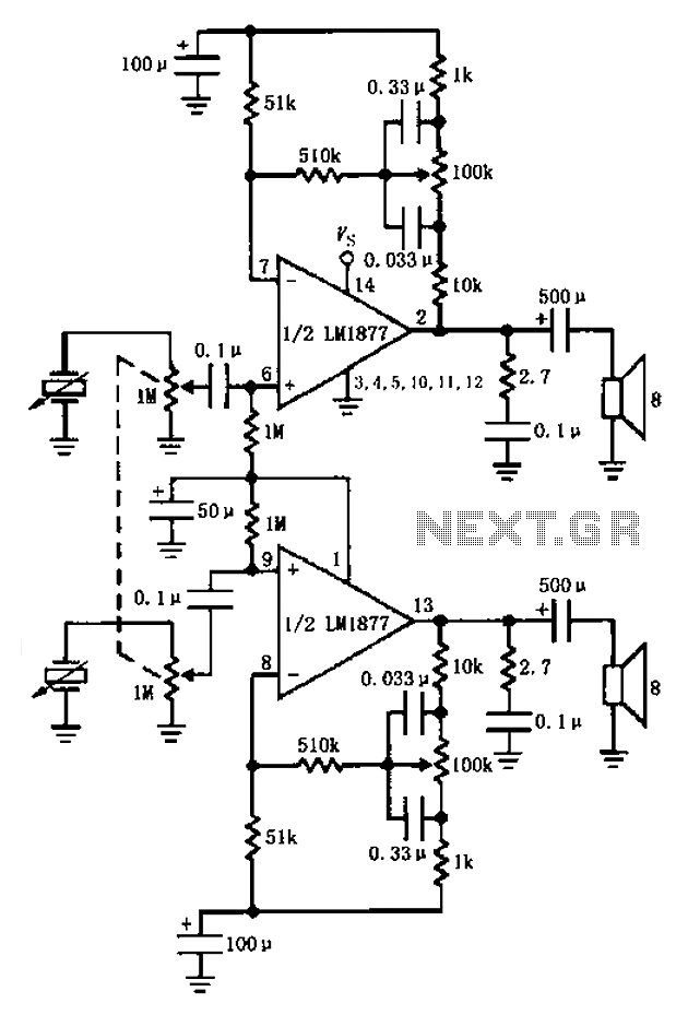
A bass player setup utilizing a stereo control is implemented through an LM1877 amplifier circuit. A cermet stereo microphone pickup is used to capture audio signals from a stereo turntable, with left and right channel outputs. The audio signals...
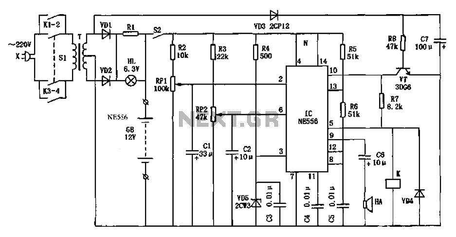
As shown in the generator start battery automatic monitor circuit diagram. The generator start battery automatic monitor circuit is designed to oversee the battery's status during generator operation. This circuit ensures that the battery remains charged and functional, preventing premature...
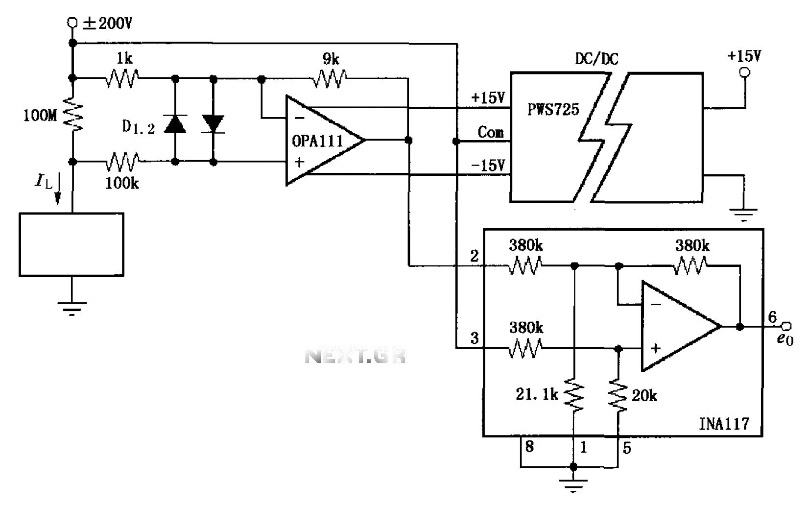
The circuit illustrated in FIG OPA111 is designed for measuring input buffer leakage current. The transistors D1 and D2, which are 2N3904 types, short the base and collector contacts while leaving the emitter open. When a power supply of...
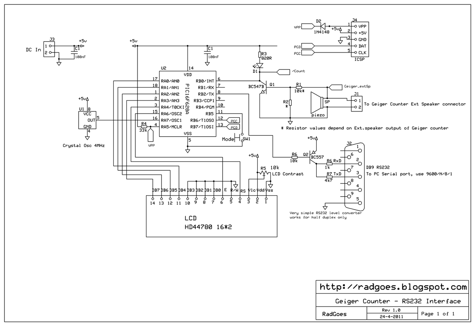
A selection of reasonably priced ex-army radiation detectors was discovered at an army surplus store. Among them was a Frieseke & Hoepfner FH40T Geiger counter, equipped with a FHZ76V energy-compensated Geiger-Mueller tube, which is sensitive to gamma (³) and...
Note that the due dates for lectures 20-25 will be rescheduled to Wednesday at 1:00 PM. Download the notes for Topic 1: Basic Components (Listen to Dr. Stienecker) and Topic 2: Power and Connections (Listen to Dr. Stieneker). Students...
Chevy S-10 Blazer Ignition Control (IC) Circuit Wiring Diagram. The Chevy S-10 Blazer ignition control circuit is a critical component in the vehicle's ignition system, responsible for managing the timing and operation of the engine's spark plugs. The circuit typically...
Warning: include(partials/cookie-banner.php): Failed to open stream: Permission denied in /var/www/html/nextgr/view-circuit.php on line 713
Warning: include(): Failed opening 'partials/cookie-banner.php' for inclusion (include_path='.:/usr/share/php') in /var/www/html/nextgr/view-circuit.php on line 713