
Chevy S-10 Blazer Ignition Control (IC) Circuit Wiring Diagram
The Chevy S-10 Blazer ignition control circuit is a critical component in the vehicle's ignition system, responsible for managing the timing and operation of the engine's spark plugs. The circuit typically includes several key components such as the ignition coil, the ignition control module (ICM), and various sensors that provide feedback to the ICM for optimal performance.
The wiring diagram for the ignition control circuit outlines the connections between these components, ensuring that the ignition coil receives the necessary signals to generate high-voltage sparks. The ICM interprets signals from the crankshaft position sensor and camshaft position sensor to determine the precise timing for spark delivery. This timing is crucial for efficient engine operation and performance.
In addition to the primary components, the wiring diagram may also depict connections to the battery, fuses, and other related circuits that provide power and protect the ignition system from electrical faults. Proper understanding and adherence to this wiring diagram are essential for troubleshooting ignition issues, performing repairs, or upgrading the ignition system.
When working with the ignition control circuit, it is important to ensure that all connections are secure and that the components are functioning correctly. Any faults in the circuit can lead to misfiring, reduced engine performance, or failure to start. Therefore, a comprehensive understanding of the wiring diagram and its components is vital for maintaining the vehicle's ignition system effectively.Chevy S-10 Blazer Ignition Control (IC) Circuit Wiring Diagram. 🔗 External reference
Related Circuits

This circuit is an enhanced front end for upgrading a transistor AM receiver. This front end is beneficial when the radio is intended to function as a tunable IF amplifier with shortwave converters. The circuit described serves as a sophisticated...
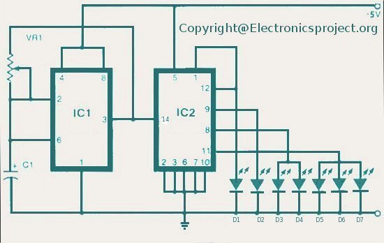
The LED indicator in this project can be used for bike indicators or car direction indicators. A 555 timer and a BCD 7490 are utilized along with several resistors, exceeding 100 in total across various electronic projects. The circuit employs...

This is a luminous flux test circuit that utilizes optical resistors. In the circuit, the optical resistor RG forms a bridge with resistors RP1, RP2, R1, and R2. RP1 is employed to balance the bridge, while RP2 is used...
A Darlington connection-type transistor is utilized for driving the coil. In this configuration, two stages of transistors are connected in series, resulting in a high current gain, where the "hfe" of the Darlington transistor is the product of the...

This intercom circuit is versatile and can be utilized in various applications. It operates at 22V, although it may function at a lower voltage (experimental testing is suggested). The circuit utilizes a loudspeaker with an impedance of 20-45 Ohms...

A diode is utilized in a temperature sensor application circuit. Silicon diodes VD1 and VD2 serve as the temperature sensors, exhibiting a temperature coefficient of silicon diodes. The circuit includes a constant current source, VT1, which provides a steady...