
Child-Proof Reset Switch

The proposed reset switch circuit enhances safety by implementing a multi-switch activation mechanism. This circuit consists of four momentary push-button switches, each connected in series. The arrangement ensures that a reset action can only be initiated when all four switches are pressed simultaneously, significantly reducing the risk of accidental resets.
The switches should be strategically placed to require both hands for activation, thereby preventing accidental engagement by children or pets. The use of momentary switches allows for temporary closure of the circuit, meaning that the reset function will only trigger while the switches are being pressed.
When designing the circuit, it is vital to select switches that are durable and capable of withstanding frequent use. The series connection of the switches means that the circuit is only complete when all four are pressed, creating a logical AND condition for the reset function.
To implement this circuit, it is recommended to use a microcontroller or a simple logic gate configuration to monitor the state of the switches. A pull-down resistor can be employed to ensure that the circuit remains in a known state when the switches are not activated.
In summary, this multi-switch reset circuit provides a robust solution to prevent accidental resets in a computer system, while ensuring that the reset functionality is still accessible when needed. This design is particularly beneficial in environments where children or pets are present, enhancing the overall safety and reliability of the computer system. The reset switch on a computer is very important. If an operating instruction threatens to wreck the internal mana gement of a computer, the reset button is often the only way of avoiding a possible disaster. On the other hand, it also could cause a disaster. It is particularly important that children or pets cannot inadvertently operate the control. The circuit proposed here should put an end to your worries in this respect. Instead of one reset switch, it is necessary to press four switches simultaneously. The chances of this happening via accident, child, or pet are negligible. The four switches are placed in positions that make it impossible to operate them all with one hand. Instead, two of them can be operated with the fingers of one hand and the other two with the fingers on the other hand. As shown, the four switches are connected in series and are intended to replace the existing switch.
Related Circuits
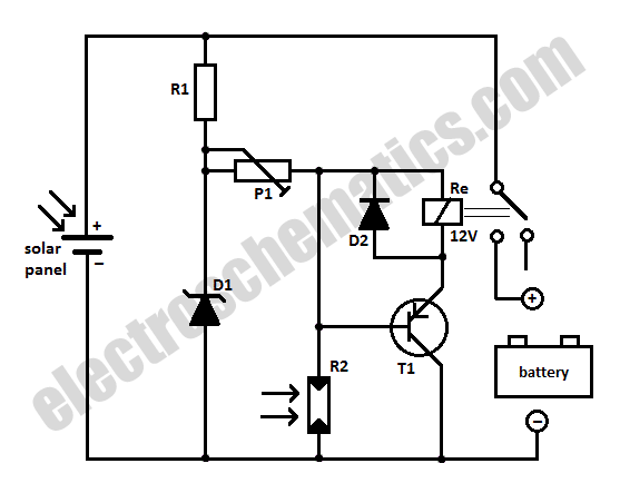
When charging a battery during the day using a solar panel, there is a risk of the battery partially discharging through the panel after sunset. This solar panel power switch circuit eliminates the need for a diode by utilizing...
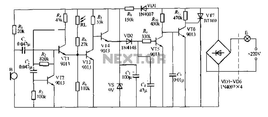
This circuit design is a sound and light control delay switch for staircase walkway lighting, featuring high voice sensitivity. In the evening, when someone walks on the stairs, their footsteps activate the electronic meter, turning on the lights. If...
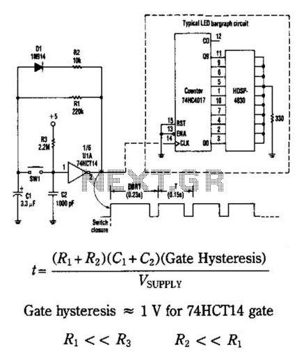
This circuit generates an output pulse when the pushbutton SW1 is pressed. It also functions as a hysteresis gate oscillator. Diode D1 and resistor R2 introduce asymmetry into the circuit. The delay before repeat time (DBRT) is influenced by...
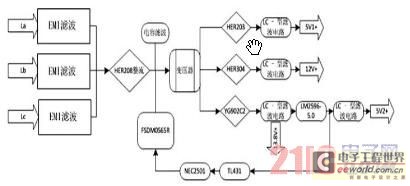
Currently, the switching power supply boasts high performance with an efficiency of 75%. The efficiency of single-scale integration switching power supplies has exceeded 90%. This advancement addresses energy concerns and enhances the performance of numerous energy-saving electrical devices. The...
This design was created to address a challenge with the tailwheel doors of the P-51 Mustang. The issue arises from the complex undercarriage sequence, which would necessitate two independent sequencers. The closing sequence involves the main gear doors opening,...
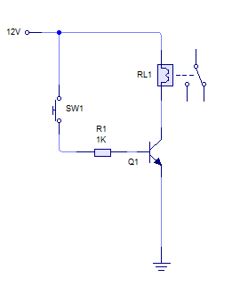
A relay is activated by grounding the low side using an NPN transistor. A pushbutton is intended to operate the transistor, thereby energizing the relay for approximately 500 milliseconds before deactivating it, while ignoring any continuous button press. Although...