
Simple Switched Servo Driver
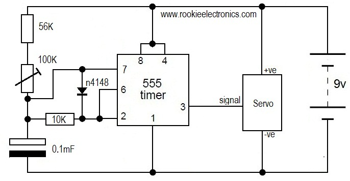
The circuit design described is centered around a robust and efficient control mechanism for the tailwheel doors of the P-51 Mustang. The core component of the system is the NE555 timer, configured in astable mode to produce a continuous square wave output. This output is utilized to control a servo motor responsible for the operation of the tailwheel doors.
The NE555 timer's frequency of oscillation is influenced by the resistors connected to its pins, specifically between pins 7 and 8. The configuration allows for a frequency range that closely matches the typical 50 Hz signal used in most radio control systems, ensuring compatibility and reliable operation. The use of both fixed and preset resistors allows for fine-tuning of the frequency and, consequently, the timing of the servo's movements.
The operation begins when the tailwheel is nearly retracted, activating a micro-switch. This switch closure triggers the servo to close the tailwheel doors. The design incorporates a mechanism to ensure that as soon as the tailwheel starts to retract, the micro-switch opens, allowing the doors to open almost instantaneously. This dual-action mechanism ensures that the tailwheel doors do not impede the retraction of the tailwheel, thus streamlining the entire sequence.
For construction, the circuit is implemented on a piece of Vero board. The process involves careful cutting of tracks, insertion of wire links, and soldering components in place. The use of PCB pins for external connections enhances ease of use and future modifications. The design is intentionally kept simple, minimizing the number of components and potential handling issues.
The inclusion of preset resistors allows for precise adjustments of the servo's end positions. This is particularly important in applications where accurate door closure is critical for aerodynamics and safety. The recommendation to use multi-turn preset resistors further enhances the ability to finely tune the system, allowing for adjustments that can accommodate variations in servo performance or mechanical alignment.
Overall, this design represents an effective solution to a complex problem in model aircraft mechanics, utilizing well-established electronic components to create a reliable and efficient control system for the tailwheel doors of the P-51 Mustang. The straightforward construction process, combined with the flexibility of the circuit design, makes it accessible for electronics enthusiasts and model builders alike.This design was created to overcome a problem I was having with the tailwheel doors of the P-51 Mustang. The problem was that the undercarriage sequence is complicated and would have required 2 independent sequencers.
The closing sequence is: Main gear doors open, Tailwheel retracts, tailwheel doors close, main gear retracts, main gear doors clos e. The complication is the main gear doors close again after the main gear extends, but the tailwheel doors remain open. Additionally the tailwheel takes 2 seconds to close (electronic servo slow) and the pneumatics for the main gear is restricted to slow their operation.
This design simply drives a servo to close the tailwheel doors once the tailwheel has retracted. It runs from the servo battery supply, but has no signal connection to the RX. When the tailwheel is almost completely retracted the wheel (or leg) closes a micro-switch. This circuit causes the door servo to move to the other end of its travel, closing the doors. almost as soon as the tailwheel starts to move the micro-switch is released and the doors open (almost instantly). The signal that the RX sends to the servos (in most systems) is pulses between 1 ms and 2ms long at a rate of 50 Hz.
This design produces pulses to drive the servo directly. The schematic and Vero Board layout are (click for full size): The circuit is quite simple to construct, having few components and no particular handling problems with the components. Firstly cut a piece of Vero board the correct size and make the cuts in the tracks as shown. Insert the wire links and solder in place. I normally use PCB pins for the external connections (much easier to work with later) and if used insert and solder these.
Fit the resistors to the board and solder. The NE555 is fitted in a socket and this will probably need trimming to sit over the 270k resistor, solder it in place. Solder the capacitor and preset resistors in place and fit the external flyleads. Bend the legs of the BC108 to fit in the board, and I recommend using a transistor base (if you can find one) to support it.
Solder it place and insert the NE555 into the socket. Build the circuit, set the preset resistors to a central position and close the micro-switch. Connect an old servo (just in case) to the output lead and power to the input. The servo should move towards one end of its travel. Adjust the 10k preset to set the servo to the desired position. Release the micro-switch and the servo should move towards the other end. Use the 20k preset to set the other end point. If you want to reverse the operation, use the normally closed contact of the micro-switch. The NE555 is a highly stable timer configured here in astable mode (oscillator) which produces a constant series of square wave pulses. The oscillation is determined by the resistances between pins 7 and 8 (R is little more complicated and can lie anywhere between 10k and 40k.
If the switch is closed the 20k preset is shorted out and the resistance is the sum of the 10k fixed resistor and the 10k preset. When the switch opens the value of the 20k preset is also added. The frequency is therefore between 49 and 41 Hz. In practice this seems near enough to the 50 Hz that most RC systems use, and I have not had any servos reject the signal (yet).
I have used 18 turn preset resistors for the above circuit as it is what I had available. Whilst any preset resistor could be used, a multi-turn preset is recommended as it allows much more accurate setting of the servo positions. If you change the type you will, of course, have to revised the board layout. C, or in our case between 0. 7 ms and 1. 4 ms with the switch closed increasing by between 0 ms and 1. 4 ms when the switch opens. As the short pulses are logic low and we therefore need to invert the signal to the servo. The 1k resistor between the positive rail and servo output pulls the signal high and the transistor conducts when
🔗 External reference
Related Circuits
A simple water level sensor or liquid level detector for measuring or detecting a required level of water, liquid, or fluid in a tank, pool, well, aquarium, washing machine, etc. The water level sensor is an essential device utilized for...
The circuit diagram represents a simple parking sensor system that measures the distance between the rear bumper of a vehicle and obstacles located behind it. The schematic consists of two main components: the transmitter and the receiver. The distance...
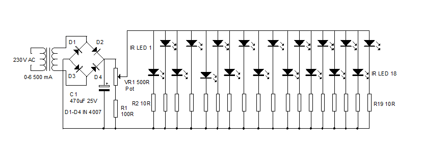
An infrared illuminator emits light in the infrared spectrum and is widely used in night vision cameras to capture images in the dark, particularly in applications such as CCTV cameras. Infrared illuminators are essential components in various surveillance and imaging...
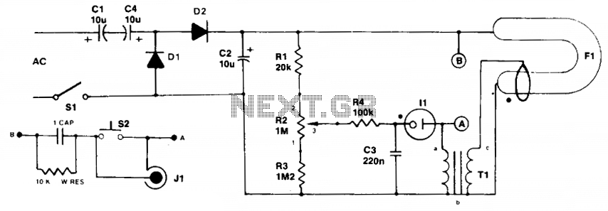
Initially, the neon and xenon lamps do not conduct and behave like very high (almost infinite) resistance. Capacitors C1 and C4, in conjunction with diodes D1 and D2, form a voltage doubler circuit, allowing C2 to charge up to...
This is likely the simplest circuit to test a servo. It tests the speed of the servo using a potentiometer to control the speed. By applying a low voltage, such as 4.5V, and adjusting the potentiometer value, the position...
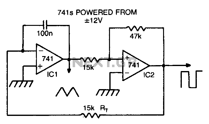
By making Rt variable, it is possible to alter the operating frequency over a 100 to 1 range. The versatile triangle/square wave oscillator has a possible frequency range of 0 Hz to 100 kHz. The described circuit features a variable...