
Christmas Light Driver

The described circuit utilizes a CMOS 4017 decade counter to manage the operation of a string of Christmas lights or similar lighting systems. The primary function of the 4017 is to sequentially activate outputs based on clock pulses, thereby allowing for dynamic control over the lighting sequence.
To interface the 4017 with the AC load, an optoisolator is employed to provide electrical isolation between the low-voltage control circuit and the high-voltage lighting circuit. The optoisolator ensures that the sensitive components of the logic circuit are protected from high voltage spikes that may occur in the lighting system.
The triac acts as a switch for the AC load, allowing the 4017 to control the power delivered to the lights. It is essential that the triac is rated for at least 200 V and 3 A to handle typical household AC voltages and the current requirements of the lighting string. The triac is triggered by the output from the optoisolator, which is activated by the signals from the 4017.
Powering the 4017 requires a minimum of 10 V to ensure that the output signals are strong enough to drive the optoisolator effectively. This voltage level guarantees reliable switching and prevents erratic behavior in the operation of the circuit.
In summary, this circuit effectively combines digital logic control with high-voltage AC switching, providing a safe and efficient means of controlling decorative lighting. Proper component selection and configuration are critical for the reliable operation of this circuit in practical applications. This circuit will enable a CMOS logic chip, such as a 4017 decode driver, to control a string of Christmas lights or other lighting. The triac should be rated at 200 V and 3 A or higher. The 4017 should be powered from at least 10 V to ensure adequate drive to the optoisolator.
Related Circuits
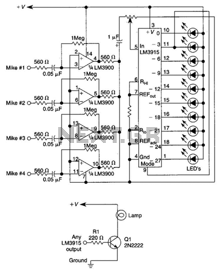
This circuit will produce an output when the sound exceeds a preset level. The LM3915 is a log-output bar graph driver. A transistor driver is used for higher current loads. To drive heavy-current loads with an LM3915 output, a...
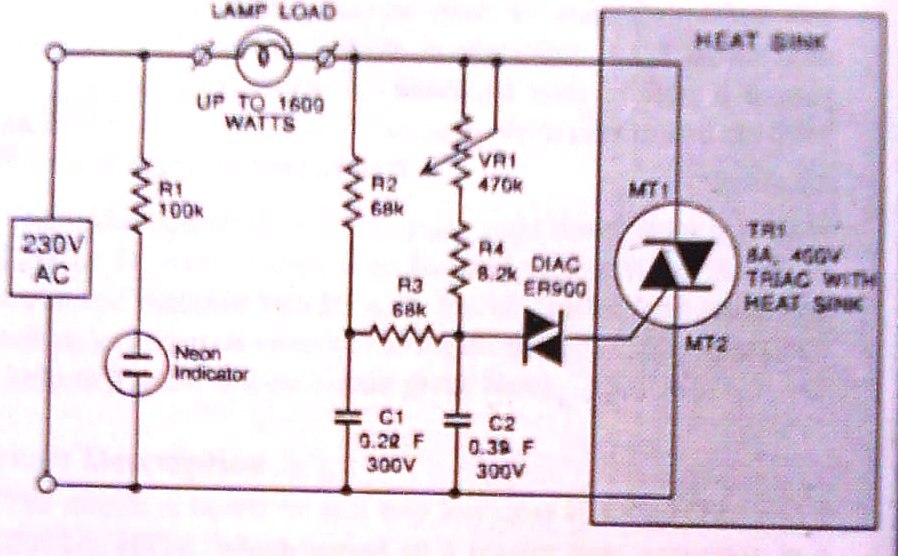
This dimmer is designed to control illumination effectively, with a power handling capacity that exceeds 1600 watts, significantly surpassing the typical 300-watt dimmers. The circuit utilizes a triac rated at 400 PIV and 8 amperes, while component VR1 allows...
Without a dedicated buck converter or white LED driver IC, it is possible to safely drive multiple standard high-efficiency white LED modules using available battery power. To design a circuit capable of driving high-efficiency white LED modules without a dedicated...
The schematic presented here can be utilized as a circuit for a car brake light or headlight flasher, designed to flash two 10-watt, 12-volt lamps in a car or any vehicle. This circuit employs a simple flashing mechanism suitable for...
This is a cost-effective and straightforward emergency light circuit developed for CircuitsToday. It is an automatic emergency lamp with daylight sensing capabilities, meaning it detects darkness and turns on automatically, while also sensing daylight to turn off. The circuit...
This circuit is a two-wire light level detector. The power supply and output signal are delivered through the same wires, utilizing a current loop. This two-wire light level detector circuit operates by using a single pair of wires for both...