
Current Loop Light Level Detector
This two-wire light level detector circuit operates by using a single pair of wires for both power and signal transmission, which simplifies installation and reduces wiring complexity. The design typically employs a photodetector, such as a photodiode or phototransistor, to sense ambient light levels. When the light intensity changes, the photodetector generates a corresponding change in current.
The current loop configuration is often based on the 4-20 mA standard, which is widely used in industrial applications for transmitting analog signals over long distances. In this setup, the light level detected by the sensor modulates the current flowing through the loop. A higher light intensity results in an increased current, while lower light levels correspond to reduced current flow. This allows for precise monitoring of light levels in various environments.
The circuit may also include a signal conditioning stage to filter and amplify the output from the photodetector, ensuring that the signal is suitable for further processing or display. Components such as operational amplifiers can be used to improve the signal-to-noise ratio, providing a more accurate representation of the light level.
In addition, the circuit can be designed with adjustable thresholds to trigger alarms or activate other devices based on specific light level conditions. This feature enhances the versatility of the light level detector, making it suitable for applications ranging from automatic lighting control to environmental monitoring systems. Overall, the two-wire configuration, combined with the current loop principle, provides an efficient and effective solution for light level detection.This circuit is two wire light level detector, we don`t separate wires for power this sensor system and for delivering the output signal. With current loop, we. 🔗 External reference
Related Circuits
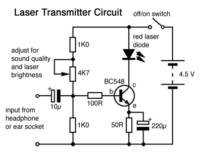
The transmission distance can be significantly increased by replacing the transmitter's red LED with an inexpensive red laser diode obtained from a dollar store. The circuit design strikes a balance between laser brightness and audio quality and volume. This...
Involvement is a modified version of the classic circuit of automatic level control signal used in tape recorders. The purchase price of the components (using TL072) does not exceed CZK 60 for a channel. For a range of entry...
Closed loop motor control is utilized for maintaining constant speed in motor operations. This means that the motor's speed is regulated to remain steady. Closed loop motor control systems, commonly referred to as servo control systems, are essential in applications...
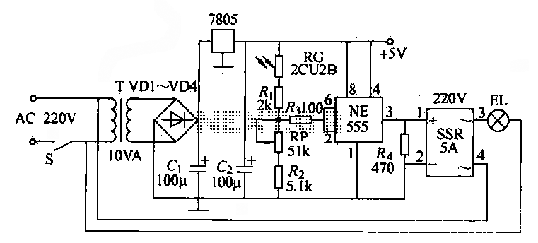
The NE555 time base circuit with an AC solid-state relay (SSR) can function as an automatic light switch circuit. The circuit diagram illustrates that during the day, the incandescent light is turned off due to the influence of the...
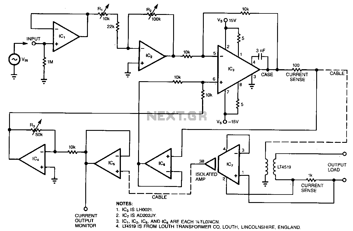
Most circuits that provide an electrical stimulus for research subjects are constant-voltage designs; this circuit is a constant-current design. Stimulator circuits must be isolated for two reasons: to ensure safety and to minimize interference. Isolated stimulators are essentially two-terminal...
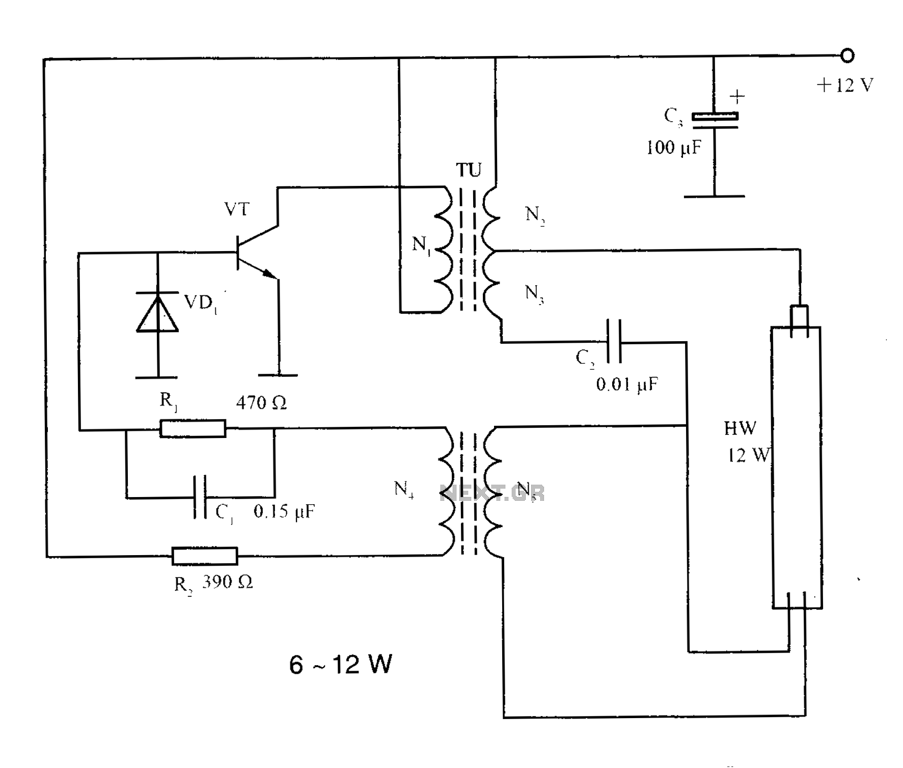
The lighting inverter circuit is designed for 6 to 12W fluorescent lamps. It operates by first bucking the mains voltage, followed by rectification and filtering to charge a battery. When the inverter is activated, it generates a high-frequency alternating...