
servo light dimmer
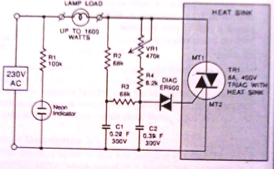
The dimmer circuit operates by controlling the phase angle of the AC voltage supplied to the load, allowing for smooth dimming capabilities. The triac serves as the primary switching device, enabling the circuit to handle high power loads without overheating. When the circuit is powered, VR1 adjusts the gate trigger of the triac, thereby controlling the amount of voltage delivered to the load.
Resistors R2 and R3 are crucial for setting the reference voltage and current through the control circuit, which influences the minimum brightness level. The capacitor C1 works in conjunction with these resistors to filter and stabilize the voltage, ensuring a consistent performance across varying load conditions.
This dimmer is suitable for a wide range of applications, from residential lighting to commercial settings, where precise control over illumination is required. The ability to handle loads greater than 1600 watts makes it particularly advantageous for use with high-wattage lighting fixtures. Additionally, the adjustable minimum brightness feature allows for customized lighting environments, enhancing both functionality and user experience.
Overall, this dimmer circuit represents a robust solution for effective illumination control, combining high power capacity with versatile adjustment features.And this is exactly what this dimmer does. One plus point is that it has a power handling capacity exceeding 1600 watts, far exceeding the ordinary 300 watt types. Any type of 400 PIV, 8 ampere triac may be used in the circuit VR1 provides illumination control. R2, R3 and C1 set the minimum brightness level which can however be altered. 🔗 External reference
Related Circuits
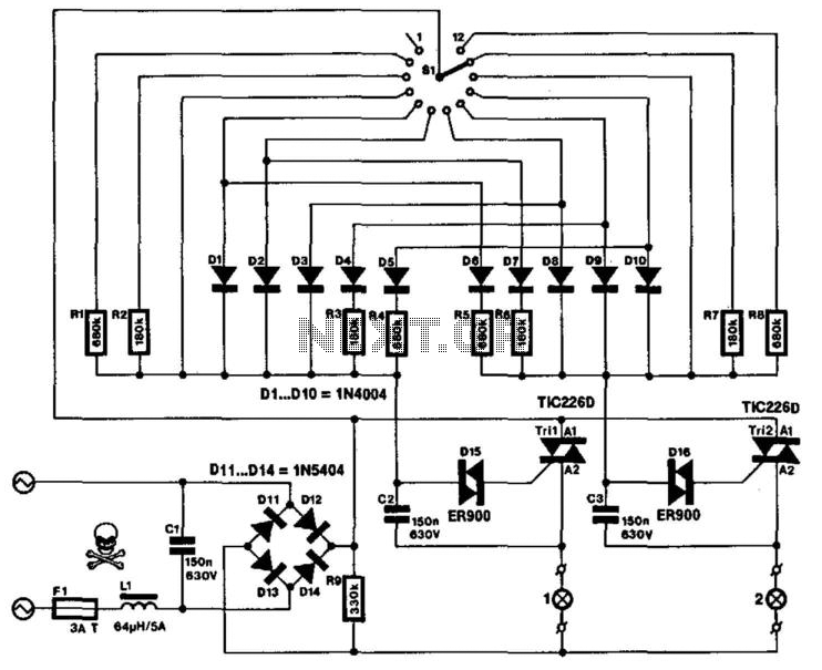
This specialized mains-operated dimmer for domestic or industrial lighting is not available in proprietary form. It enables brightness control of two groups of lights simultaneously. The possible combinations of brightness are outlined in a table. Continuous brightness control for...
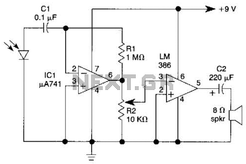
This light-wave receiver comprises a 741 operational amplifier functioning as a preamplifier and an LM386 operational amplifier serving as a power amplifier. The gain control is managed by a potentiometer labeled R2. Various types of detectors can be utilized...
The circuit diagram of an IC Controlled Emergency Light with Charger, also known as a 12V to 220V AC inverter circuit, is presented here. This circuit features automatic activation of the light during mains failure and includes a battery...
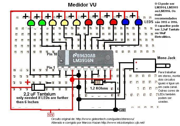
A post related to a do-it-yourself project for creating a VU meter and homemade rhythm lights that are easy to assemble. The project involves designing and constructing a visual audio level meter (VU meter) that responds to sound levels, as...
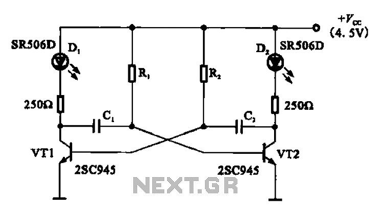
The multivibrator flashing light emitting diode (LED) display driver circuit can be utilized in toys, creating flashing effects in the eyes of animals or monsters. This circuit employs a multivibrator configuration, typically a 555 timer IC or a similar component,...
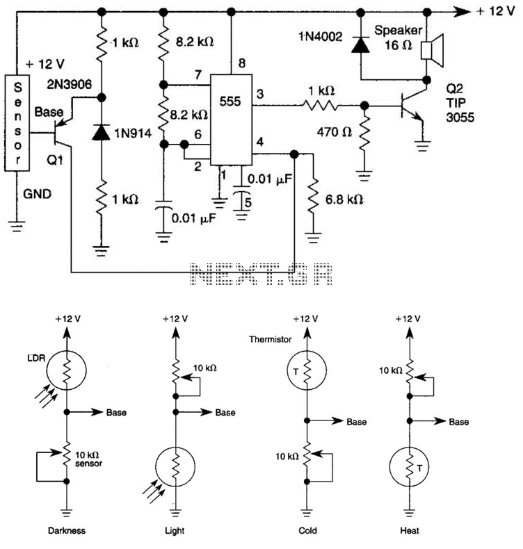
The tone generated by a 555 oscillator can be activated by heat or light, which causes Q1 to conduct transistor Q2 (TIP 3055). Q2 (TIP 3055) functions as an audio amplifier and speaker driver. The circuit utilizes a 555 timer...
Warning: include(partials/cookie-banner.php): Failed to open stream: Permission denied in /var/www/html/nextgr/view-circuit.php on line 713
Warning: include(): Failed opening 'partials/cookie-banner.php' for inclusion (include_path='.:/usr/share/php') in /var/www/html/nextgr/view-circuit.php on line 713