
car brake light or headlight flasher
This circuit employs a simple flashing mechanism suitable for automotive applications. The primary components include a timer IC (such as the 555 timer), which is configured in astable mode to generate a square wave output, effectively controlling the on-off cycling of the lamps.
The circuit is powered by the vehicle's 12-volt power supply, ensuring compatibility with standard automotive electrical systems. The two 10-watt lamps are connected in parallel to the output of the timer, allowing them to flash simultaneously.
To achieve the desired flashing effect, the frequency and duty cycle of the timer can be adjusted by changing the resistor and capacitor values connected to the timing pins of the IC. A typical configuration might use a capacitor in the range of microfarads and resistors in the kilo-ohm range to set a suitable flashing rate, which can be visually appealing and effective for signaling.
In addition to the timer, a transistor may be included in the circuit to handle the current required by the lamps, ensuring that the timer IC operates within its safe limits. A diode can also be integrated to protect against back EMF generated by the inductive load when the lamps are turned off.
Overall, this schematic provides an efficient and straightforward solution for enhancing vehicle safety through improved visibility of brake lights or headlights, making it a valuable addition to automotive lighting systems.The schematic shown here can be used as a circuit for Car brake light or headlight flasher for flashing two 10 watt 12 volt lamps in car or any vehicle. .. 🔗 External reference
Related Circuits
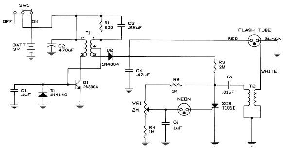
Caution! This strobe light circuit operates on 220V, making measurements and experiments extremely hazardous, even after disconnecting it from the mains. The strobe light circuit is designed to produce high-intensity flashes of light at specified intervals. It typically consists...
This was designed to flash a pair of LEDs to be mounted on the wing tips of a Parkzone Citabria R/C (remote control) airplane. The unmodified Parkzone Citabria only weighs 20 grams (about 0.7 oz), so weight, and therefore...

This unit is designed to connect to an existing car stereo amplifier, providing the additional "punch" often desired in music playback by driving a subwoofer. Since very low frequencies are omnidirectional, a single amplifier is needed to power this...
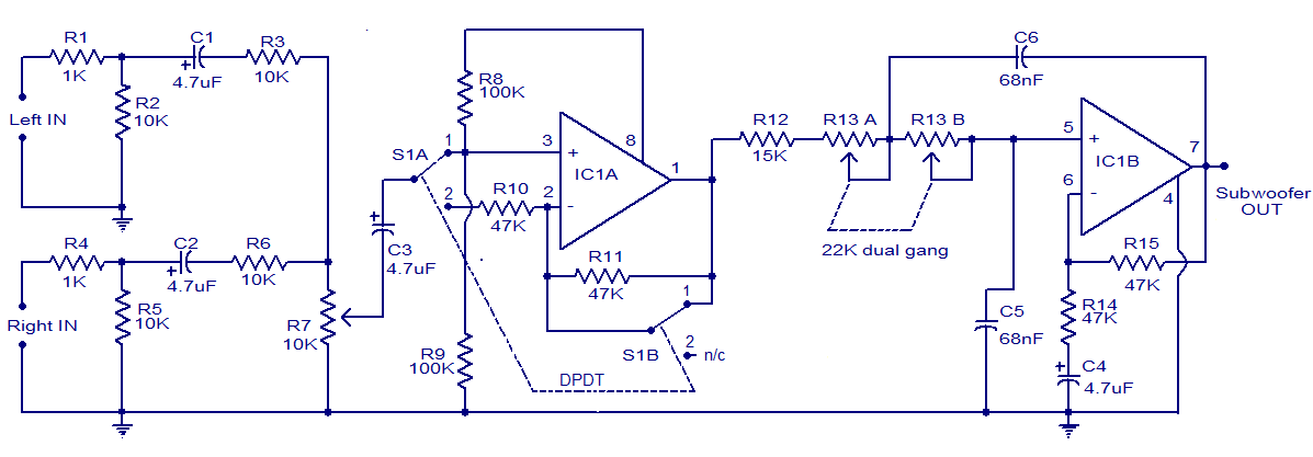
The circuit diagram depicts a simple subwoofer filter that operates on a 12V DC supply, making it particularly useful for automobile subwoofer applications. This circuit functions as a low-pass filter, with an adjustable pass frequency ranging from 60 to...

Only one channel of this circuit is shown. The other is practically identical. The input to the circuit, taken from the speaker output of a car radio, is divided into two paths. In one path, a high-power divider network...

A simple light fence security beeper is presented. This circuit can function as a door alarm, gate alarm, pathway alarm, etc. It can be powered by any 12 Volt DC power supply. The operation of this circuit is straightforward....