
Cipher scheme of the module of infrared remote-control between two parties of intellectual family

This control system employs a single-chip microcontroller, which serves as the central processing unit for managing the lighting control functions. The microcontroller is programmed to interpret the incoming signals from the infrared receiver and execute corresponding commands to adjust the lighting conditions. The system architecture is designed to ensure a seamless interaction between the transmitter and receiver, allowing for real-time adjustments to the lighting environment.
The infrared transmitter is equipped with a user interface, typically consisting of buttons that represent different lighting commands. Each button press triggers the signal generating circuit to produce a specific modulated infrared signal, which is then emitted by the infrared LED. The modulation technique used may include pulse width modulation (PWM) or frequency modulation, ensuring that each command is uniquely identifiable by the receiver.
On the receiving end, the infrared receiver is designed to capture the modulated infrared signals and convert them back into electrical signals. The received signals pass through an amplification stage to enhance their strength, followed by a demodulation stage that extracts the original command signal from the modulated carrier wave. The command detection circuit interprets the demodulated signal, allowing the microcontroller to determine the intended action, such as turning the lights on or off or adjusting their brightness.
In terms of safety and efficiency, the system is designed to minimize power consumption while maintaining high performance. The use of low-power components and efficient coding practices ensures that the system operates reliably without excessive energy use. Additionally, the integration of advanced computer technology allows for future upgrades and expansions of the system, enabling the incorporation of additional features such as scheduling, remote monitoring, and integration with other smart home devices.
Overall, this intelligent lighting control system exemplifies the convergence of modern technology and user-centric design, facilitating a more convenient and efficient approach to home lighting management.This system is a control system based on one-chip computer, control the system light in remote-operated way. This scheme mainly solves transmission and receiving of the signal, the program manipulation to different signals after the the signal one is dealt with and received, adjust through software programming realization switch and luminance to the bulb.
The intellectual home furnishing refers to utilizing advanced computer technology, network communication skill, comprehensive wiring technology, it is here to combine every seed system related to family life organically, through managing as a whole, let the family life be more comfortable, more safe, more effective. With the development of people`s life lateral improvement and electron technology, the home furnishing is intelligent to begin to come into our daily life.
People are not satisfied with the key-type hand-operated switch to control the lamps and lanterns, thus develop the telecontrol system of more high professional illumination control of the intelligent level, its low cost, high in quality, it is flexible and convenient to employ. And because of the characteristic with small, low power dissipation, function are strong, low cost, infrared remote-control command is to employ most extensive kind of communication and remote control means at present.
Infrared remote-control command is to utilize infrared rays also call the infrared light To transmit the control signal, realize the remote control of the control objective. Particularly, are emitted the command signal of infrared rays by the projector, is received by the receiver and deals with and discerns the signal, and then realize the remote control of different functions of the control objective according to different signals received finally through the corresponding control chip.
The infrared rays projector transmits the device to make up from order key set, generating circuit of the signal, modulator circuit of frequency, driving circuit and infrared rays, as shown in Fig. 1. When the order key is pushed, the command signal generating circuit produces the required control command signal.
The command signal of control here distinguishes with some different characteristics. The characteristic of the commonly used differentiation command signal is frequency characteristic and code block characteristic, instant using and different frequency or different coded telecommunication coaxialities represents different orders. The different command signals undergo frequency modulation, drive the infrared rays to launch the device from the driving circuit finally, send out the command signal of infrared remote-control command.
The infrared receiver is received device, leading amplifying circuit, demodulation circuit of the signal, order detection circuit to make up by the infrared rays, such as Fig. 2. When the infrared rays receives the device to receive the infrared rays command signal of the projector, it turns the infrared optical signal into an electric signal and sends into the pre-amplifier and amplify, by the detecting circuit of command signal after demodulation of demodulator the detection of command signal, realize various operation.
It must choose the way in which the signal instruction conveys first to want the remote control function of the implementation system. On the basis of the remote-operated way and user`s occasion, may go on various characteristic of these control signal to make up and encode.
Such as the mode of combination of the voltage direction, the mode of combination of the phase place of electric signal, the mode of combination of the amplitude of the electric signal, the mode of combination of the frequency, pulsing width, the modes of combination of phase place, isoparameter of range and mode of combination of pulse code, etc. The mode of combination of the pulse code has g 🔗 External reference
Related Circuits
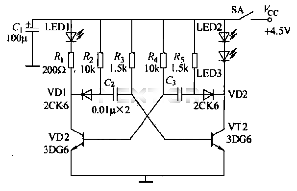
The infrared transmitter circuit, as depicted in Figure 18-la, utilizes transistors VT1 and VT2 along with RC components to create an astable multivibrator. The circuit operates with VT1 and VT2 receiving base bias from resistors, and closing switch SA...

This application note discusses the use of SEPIC power modules to supply the necessary power for driving high-brightness LED arrays. These arrays serve as display backlights and necessitate a wide dimming range. The SEPIC configuration offers an efficient and...
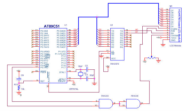
In the circuit presented, the LCD module's Command Register is configured at address 00H and the Data Register at address 01H. Consequently, writing data to address 00H will be interpreted as a command for the LCD, while writing to...
The ELM622 by ELM Electronics is a preprogrammed PIC that converts commands from a Sony infrared remote control into a serial data stream. An IR receiver utilizing the ELM622 does not require kernel modifications. This project demonstrates how to...
This is an infrared (IR) proximity detector circuit. A matched infrared emitter and detector pair is used in this circuit. The voltage-controlled oscillator is involved. The infrared proximity detector circuit utilizes a matched pair of infrared emitter and detector components...
This circuit utilizes a photoelectric coupler to achieve 100GΩ isolation between a TTL (Transistor-Transistor Logic) circuit and a relay circuit. This configuration effectively prevents relay noise and peak voltage from affecting the TTL circuit. When the TTL input signal...