
Infrared (IR) Proximity Detector
 Proximity Detector")
The infrared proximity detector circuit utilizes a matched pair of infrared emitter and detector components to sense proximity. The circuit typically consists of an infrared LED (emitter) that emits infrared light and a photodiode or phototransistor (detector) that receives this light. When an object comes within a certain range of the detector, the reflected infrared light triggers a change in the output signal.
The voltage-controlled oscillator (VCO) plays a crucial role in modulating the emitted infrared light. By varying the frequency of the emitted signal, the circuit can differentiate between ambient light interference and the reflected signal from the target object. This modulation allows for improved detection accuracy and range.
The circuit may also include additional components such as resistors, capacitors, and operational amplifiers to condition the signal and provide necessary gain. The output can be configured to drive an indicator LED or trigger a relay, thus providing a visual or mechanical response to the detected proximity.
In summary, the IR proximity detector circuit is a versatile and effective solution for applications requiring object detection, such as in automation systems, security sensors, and robotic navigation. The integration of a voltage-controlled oscillator enhances its performance by allowing for more precise detection capabilities.This is infrared (IR) proximity detector circuit. A matched infrared emitter and detector pair is used in this circuit. The voltage controlled oscillator.. 🔗 External reference
Related Circuits
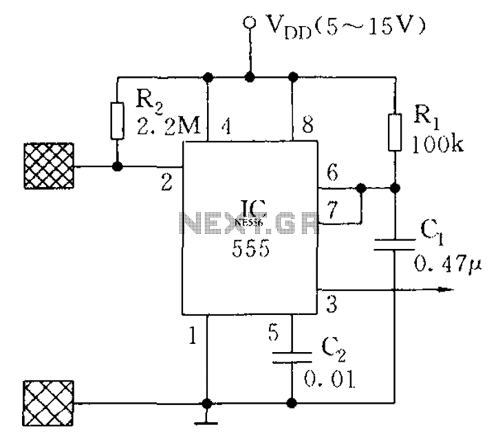
The proximity switch using the 555 timer functions as a monostable trigger circuit. The trigger pin (Pin 2) of the 555 timer is connected through a large resistor (R2) to the positive supply voltage (VDD) and is in a...
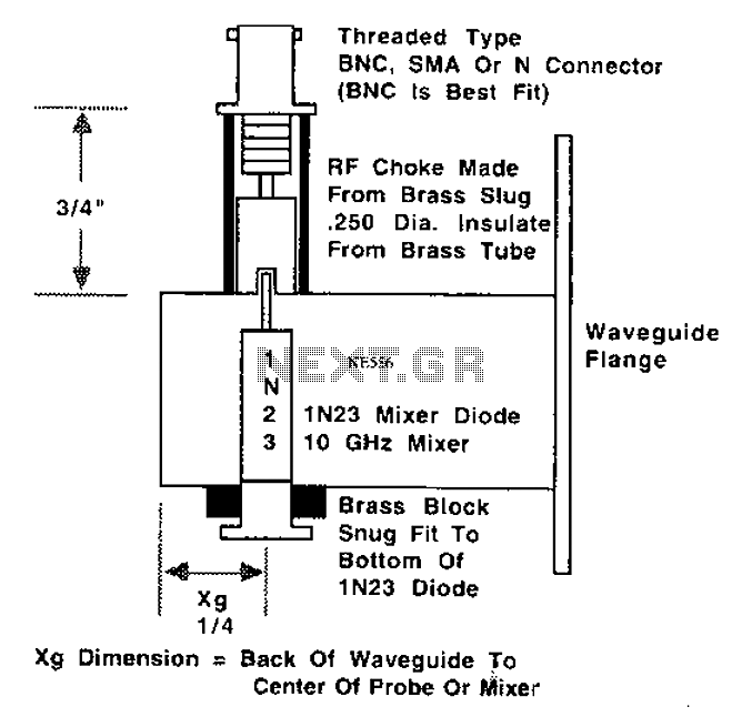
This is a 10 GHz frequency amateur radio waveguide detector. The 10 GHz amateur radio waveguide detector is designed to operate within the microwave frequency range, specifically targeting the 10 GHz band commonly used in various amateur radio applications. The...
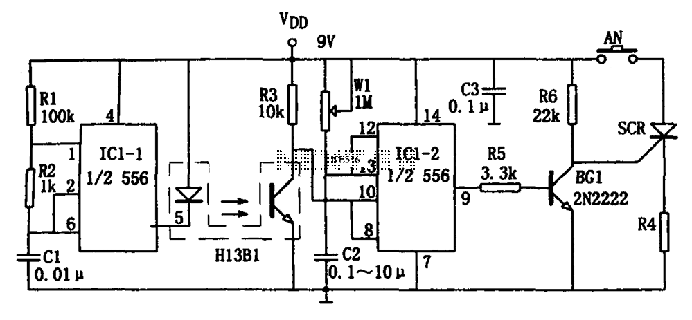
The circuit shown is a photoelectron pulse missing detection circuit. It includes an optoelectronic slotted switch H13B1, a dual time base circuit using a 556 timer IC, and several RC components that form a one-shot multivibrator. The design incorporates...
This circuit is a motion detection sensor that utilizes a light source and detector as an infrared motion detector. It incorporates components such as a light-emitting diode (LED), a phototransistor, a transmitter, a receiver, an NE555 timer configured as...
The primary function of this circuit is to activate a buzzer or a relay whenever the humidity level reaches a specified threshold. The main component is a memory element based on a flip-flop made up of gates and integrated...
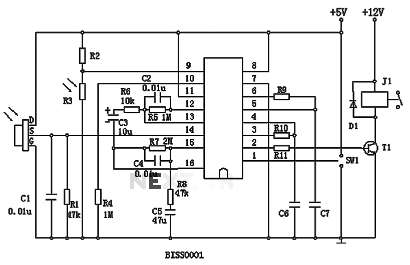
BISS0001 is a high-performance integrated circuit designed for sensor signal processing. It is used in conjunction with pyroelectric infrared sensors and requires only a few external components to function as a passive pyroelectric infrared switch. This circuit can automatically...