
Infrared remote control a dimming circuit

The infrared transmitter circuit employs a configuration of transistors and resistors to achieve its function as an astable multivibrator. The transistors VT1 and VT2 are pivotal in generating the oscillation necessary for infrared light emission. The switching action of these transistors is controlled by the charging and discharging of the capacitor C3, which is influenced by the resistors R4 and the diode VD2. The interaction between these components establishes a feedback loop, ensuring that once VT1 is turned off, VT2 can turn back on, maintaining a continuous oscillation.
The infrared receiver circuit is designed to interpret signals from the infrared transmitter. The KA2184 chip acts as a signal processor, detecting the infrared signals and converting them into a usable output for dimming control. The output from the KA2184 is crucial as it directly influences the operation of the TRIAC, which modulates the power delivered to the lamp. The dimming functionality is enhanced by the ability to adjust the conduction angle of the TRIAC, allowing for smooth transitions between different brightness levels.
The LS7232 PMOS IC is specifically chosen for its characteristics, requiring careful attention to power supply connections to function correctly. The use of AC power with appropriate rectification and filtering components ensures stable operation. The buck capacitor's role in conjunction with the inductance is essential for minimizing electrical noise, which can adversely affect the performance of the dimming circuit and other connected devices. Overall, this circuit configuration demonstrates an effective solution for infrared remote control dimming applications, combining reliable signal processing with practical power management techniques.(1) infrared transmitter circuit of the infrared transmitter circuit shown in Figure 18-la. By transistors VT1, VT2 and RC components and the like more than a flop. Multivibrator works; Kun brother were VT2, VT1 base bias resistors, closing the switch SA plus power supply voltage is, VTZ priority conduction, the collector electrode was low Tun "O", this low level by VD2, C3 is coupled to the base of VT1, VT1 cut so stop. After VT2 conduction, R4, VD2 and VT charge to G, the charge is to make the C band left and right positive negative charge, so that the base of VT1 potential begins to rise.
When the base voltage rises to a certain value, VT1 conduction, the collector under variable level jump through VDI, the island was added to the VT2 base, so that VT2 by conduction to cutoff. After a short while, rr, 1 turned off, VT2 conduction. vri, VT2 alternately turned on and off, so to the cycle continues. So called astable multivibrator. The oscillation frequency depends on the charge and discharge time constant R, G, and Ra, the island.
VT1, VT2 after the start-up alternately turned on and off, then on its collector LED2, LED3 and LED1 alternately emit infrared light red shade. LED visible light is used to monitor the oscillator is working properly or not, that is the working condition.
(2) When the infrared receiver circuit infrared receiver receives the remote control signal emitted by the transmitter, after KA2184 processed by pin output low. This added directly to the VT low base, it is turned on, its collector current output secluded island formed a high-level output end of the.
This was added to a high level by withered optical circuit LS7232 auxiliary input ( feet). As the dimming control signal. Reception circuit shown in FIG. 18-lb, it is an infrared remote control dimmer circuit, when its trigger input pin, feet it will be a continuous control of the control pulse output TRIAC conduction angle, so that the TRIAC conduction angle 41. -160. Changes between. With bidirectional thyristor. Tube conduction angle changes, the lamp becomes bright or dark by the light dimmed, thus realizing the lamp dimming control.
In the dimming process when required by the dark to bright lights, press and hold the button on the remote control transmitter continuously transmits a control signal. Then you can see the lights gradually brighten, when it reaches the desired brightness, immediately release the PTT button, then the brightness of the lamp will stay in this position.
If even continued the next, from the bright lights will gradually darken until extinguished.. Note: LS7232 is a PMOS type IC, so its power polarity with conventional CMOS circuits to move the anti-that it should be connected to the negative terminal Vm power supply, while the positive end of the rainbow should be connected to the power supply. The circuit power is still using AC power supply, capacitance G buck, rectifier diode VD1 half crossing.
And other different capacitor step-down power supply circuit is that the power of the buck capacitor in parallel with a G 220vH inductance, its role is to absorb harmonics generated by the LS7232, prevent its interference with other appliances through power line .
Related Circuits
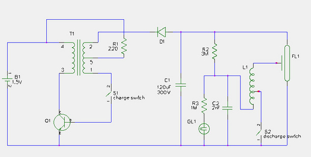
This document provides a step-by-step guide for modifying a disposable camera flash unit to serve as a power supply for a Geiger tube. The process involves removing the flash tube and trigger transformer from the circuit board by gently...
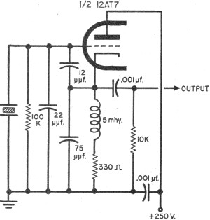
To update the fundamental oscillator circuits, simply replace the transistors with tubes. Alternatively, if one owns a vintage vacuum tube radio, it may be of interest to learn about historical practices. In general, the foundational principles of electronic circuits...
The induction coil detects the magnetic field flux during phone calls, amplifies the signal, and triggers the LED. These circuits are designed for the phone to rest on the pickup coil. The electromotive force (emf) from the bell electromagnets...
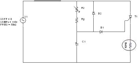
The diagram illustrates an R-C-Diode circuit that provides full half-cycle control (180 electrical degrees). During the positive half-cycle of the SCR anode voltage, the capacitor charges to the trigger point of the SCR, a process governed by the RC...

This circuit design for an amplifier was created to address the gap in the 3-10 Watts power output range of audio amplifiers available in RED Free Circuit Designs. A straightforward, low-component-count amplifier was developed based on the successful 45...
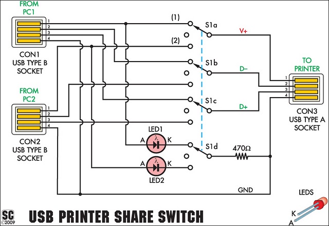
This device enables two computers to share a single USB printer or other USB devices such as an external flash drive, memory card reader, or scanner. A rotary switch is used to select the PC that will connect to...