
Circuit & Code for Typing Assistant using 8051 microcontroller & PS/2 port of Computer
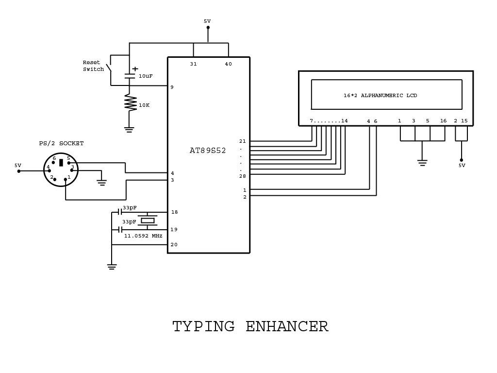
The Typing Assistant project utilizes the 8051 microcontroller, specifically the AT89S52 variant, to create an interface with a PS/2 keyboard. The PS/2 keyboard allows users to input data, which the microcontroller processes and subsequently sends to the computer. The project encompasses both the hardware circuit design and the necessary software code to facilitate this interaction.
The circuit design includes the following key components: the AT89S52 microcontroller, a PS/2 connector, and passive components such as resistors and capacitors. The PS/2 connector is wired to the microcontroller, allowing it to read the keyboard signals. The microcontroller is powered by a regulated power supply, typically 5V, and is connected to the computer via a serial communication interface.
In terms of software, the code written for the AT89S52 is responsible for interpreting the signals received from the PS/2 keyboard, converting them into a format that can be understood by the computer. This involves reading the scan codes generated by the keyboard, processing them, and then transmitting the corresponding ASCII values over the appropriate communication protocol.
The project serves as an educational tool, illustrating the principles of microcontroller programming, interfacing, and serial communication. It provides insights into how peripheral devices can be integrated with microcontrollers to enhance functionality and user interaction. By successfully implementing this project, users gain practical experience in electronic design and embedded systems development.Project with Circuit & Code for Typing Assistant using 8051 microcontroller (AT89S52) and PS/2 keyboard port of Computer. The project also explains the interfacing of PS/2 port of computer with 8051 microcontroller 🔗 External reference
Related Circuits
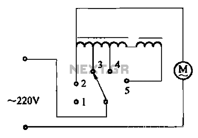
The circuit illustrated in Figure 3-2 features a loop reactor governor that incorporates a series reactor. The reactor can be constructed using a TV choke and is designed to be approximately 3mm in height. It utilizes a strength wire...
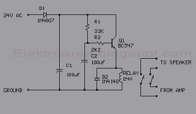
This circuit was designed for an audio amplifier project to control the speaker output relay. The primary function of this circuit is to manage the relay that activates the speaker output in the audio amplifier. The circuit introduces a...

This circuit demonstrates a dynamic AC signal level display drive, which can be utilized for audio level display purposes. The AC signal detection and drive control are achieved using the BA6124 integrated circuit, along with five external colored light-emitting...

This inexpensive FM radio receiver antenna booster utilizes the BF324 TO92 style PNP transistor in a grounded-base configuration. The circuit can be employed as a... The FM radio receiver antenna booster circuit is designed to enhance the reception capabilities of...
This voltage-to-frequency converter circuit features a voltage-controlled oscillator with a deviation of 0.5%. The integrated circuit IC1 functions as a multivibrator, generating rectangular impulses of equal width. The output frequency is adjustable via the U1 voltage. The D3 diode...
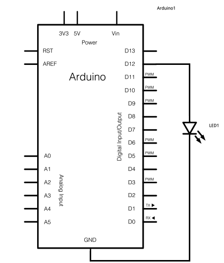
The schematic for this project consists of adding a single 5mm LED to one digital output port on the Arduino. The main components in the schematic include the Arduino Uno, a 5mm LED, and a USB cable. The left...