
Voltage to Frequency Converter Circuit
The voltage-to-frequency converter (VFC) circuit operates by converting an input voltage into a corresponding frequency output. The core component, IC1, is configured as a multivibrator, which generates square wave pulses. The frequency of these pulses is directly proportional to the input voltage applied at U1, allowing for precise control and adjustment. The design includes a feedback mechanism facilitated by the D3 diode, which serves to stabilize the circuit by negating the effects of R4 and P1, ensuring that the output remains consistent and reliable.
Diodes D1 and D2 play a critical role in temperature compensation by generating a small bias current that helps maintain the circuit's performance across varying thermal conditions. The inclusion of P2 allows for fine-tuning of the offset voltage, which is essential for achieving accurate frequency output in response to the input voltage.
The versatility of this VFC makes it applicable in various electronic systems, including signal generation, modulation schemes, and telemetry applications. Its capability to provide a stable frequency output from a variable voltage input makes it an invaluable component in modern electronics, where precision and reliability are paramount. This circuit can be adapted for specific applications by modifying the resistor-capacitor (RC) timing network or replacing it with an inductor-capacitor (LC) configuration, depending on the desired frequency range and characteristics.
Overall, this voltage-to-frequency converter circuit exemplifies a robust and adaptable solution for converting voltage signals into frequency outputs, suitable for a multitude of applications in electronic design and development.This voltage to frequency converter circuit has an oscillator that is voltage controlled and has a small, 0. 5% deviation. IC1 function as a multivibrator and produces rectangular impulses with equal width. The output frequency can be easily adjusted with the help of U1 voltage. D3 diode is required because we want to eliminate R4 and P1 influence. D1 and D2 diodes produce a small flow of temperature. With P2 we adjust the offset voltage. Because of its high quality, this voltage-frequency converter (VCO) can be used in a large field of applications. Hi Jim, thanks for the reply. Though I am old, and been at this a while now, seems the math involved in electronics takes all the want to out of me on alot of projects.
I get alot out of accomplishing working circuits, but the math has never been something that ever stuck with me, even with the use of calculators, I have to re-read the process over and over to formulate an anserw. I am trying to get a 2450Mhz circuit put together. My eyes suck, but have been trying to reverse engineer a salvaged Microwave oven circuit board to find out how to resonate an old M.
O. T. for an exsperiment I am doing. I cannot tell on some of the boards I have if it is the Ic doing the oscillations or the pezio buzzer or some other HF switching triac Any Ideas All the salvaged boards, I have three are from digital display and have dig processors on the same boards, so far I have found no switching transistors so I assume one of the IC chips involved is the VIBRATOR Oscillator. Would this circuit with modifications to the RC or replaced with LC work Thanks again Jim, I am not wanting to build microwave oven or transmit a signal, I came to Mhz because of a video I saw.
It required the same Hz as used for Microwave Ovens. I have alot of old stuff I salvaged electronics and began looking at C-boards to see HOW it was done. and while waiting on this friend I was at my bench and looking over an old Cell I had built, also at my bench was a Coleman tm 1500watt inverter and home built fullwave bridge rectifyer so I began messing around with those and a 12v truck battery, a quart of Distilled water.
in the middle of the Sahara and opened it! only this was a quart sized open 4 ³ S. S. 8 ³ long pipe with a capped bottem to hold the water in the cell. Since then I have been trying to duplicate this method but with a bit more control, because it was toooo fast, and produced heat after refilling over and over with distilled water. I saw a guy who might have hit on the same methode who is in the process of commercialing it so he is secretive in the method process, but 2450Mhz was communicated during the video.
🔗 External reference
Related Circuits
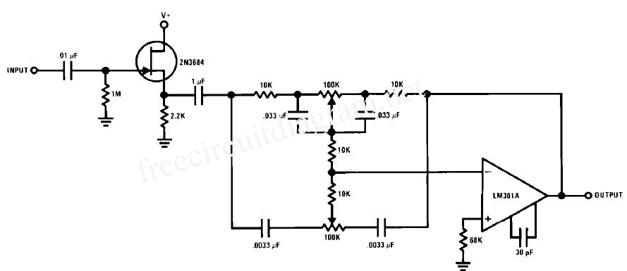
This circuit is a simple series tone control circuit utilizing the OP-Amp LM301A. The JFET 2N3684 provides high input impedance and low noise characteristics for the feedback buffer in the op-amp-based tone control. The tone control circuit described employs an...
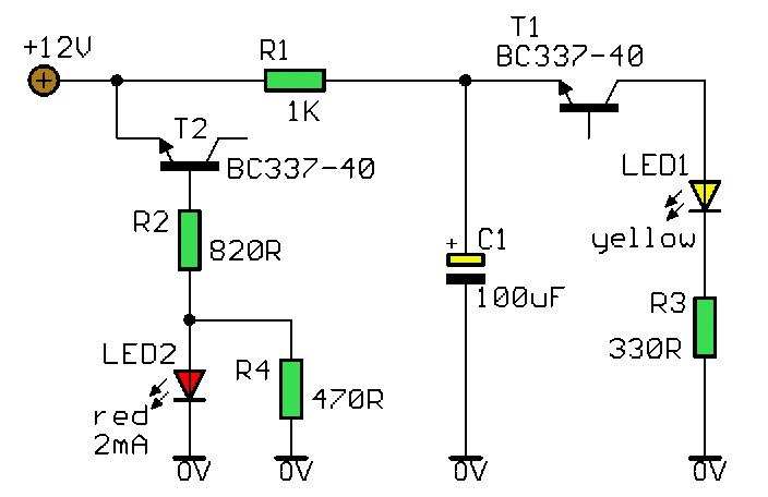
This circuit clearly indicates the supply voltage level in a larger device. When the indicator receives a stable 12 volts, LED1 emits a steady yellow light. If the input voltage drops below 11 volts, LED1 begins to blink, with...
Even though the power was off, there was AC present at the handle plug, and a short circuit occurred. Upon disassembly, a blown transistor was discovered. An attempt was made to fix the issue, but after one month and...
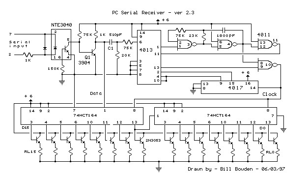
This circuit requires physical connections to be made to the computer's serial port (COM1 or COM2). It is generally considered difficult to cause harm to oneself or the computer through improper connections to this port; however, there is no...
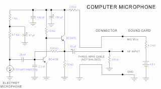
This microphone circuit was submitted by Lazar Pancic from Yugoslavia. The sound card for a PC typically features a microphone input, speaker output, and occasionally line inputs and outputs. The microphone input is designed specifically for dynamic microphones with...
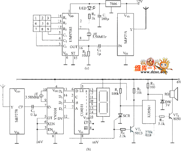
The circuit utilizes a dual sound multi-frequency encoding signal to modulate the emitted carrier frequency, forming a DTMF encoding wireless calling system. It incorporates the DTMF encoding circuit UM97085 and the decoding circuit YN9101 to create a micro wireless...