
circuit and program to interface mt8870 with at89s51

The circuit designed to interface the MT8870 DTMF decoder with the AT89S51 microcontroller is aimed at decoding Dual-Tone Multi-Frequency (DTMF) signals, which are commonly used in telephone systems. The MT8870 is a highly integrated DTMF receiver that converts the DTMF signals into a binary-coded decimal (BCD) output. The AT89S51 microcontroller, part of the 8051 family, is utilized to process these signals and perform further actions based on the decoded output.
The circuit typically includes the following components: the MT8870 IC, the AT89S51 microcontroller, a set of resistors and capacitors for signal conditioning, and a power supply circuit. The MT8870 receives the audio signals from the telephone line, filters and demodulates them, and generates a corresponding BCD output that represents the pressed keys on the telephone keypad.
The interfacing between the MT8870 and the AT89S51 involves connecting the BCD output pins of the MT8870 to the input pins of the microcontroller. The microcontroller is programmed to read these inputs and execute predefined actions, such as lighting an LED or activating a relay, based on the DTMF signals received. The program running on the AT89S51 may also include debounce logic to ensure that only valid signals are processed, as well as error handling routines for robustness.
In summary, this resource provides a practical application for interfacing a DTMF decoder with a microcontroller, demonstrating how to effectively decode and utilize telephone signals in embedded systems. The project serves as a valuable reference for engineers and hobbyists looking to implement similar functionalities in their designs.Binu submitted a new resource: Circuit and Program to Interface MT8870 with AT89S51 (version 1.0) - Decoding the DTMF signals from the telephone line .. 🔗 External reference
Related Circuits
Dark Activated Switch or Porch Light Switch. This circuit activates a relay when the light level drops below a preset threshold. The light sensitivity can be adjusted using variable resistor VR1, and the relay contacts can control an external...
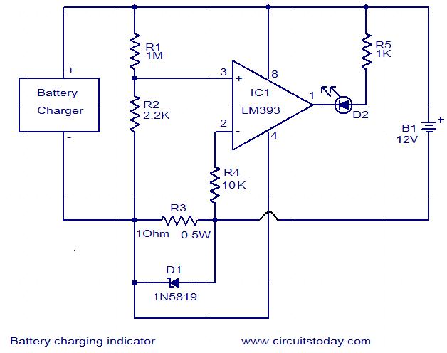
This simple circuit can be used to monitor whether a battery is charging. The voltage comparator IC LM393 is the core component of this circuit. The LED D1 will remain ON whenever there is at least 25 milliampere current...
This self-powered interface circuit electrically isolates the TxD and RxD lines from the PC serial port, protecting the PC from direct connection to hazardous voltages. The isolator is designed to provide electrical isolation between a computer and the equipment...
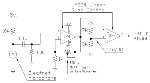
Instructions for creating a Clap-Clap On/Clap-Clap Off switch circuit. This guide provides the necessary information for constructing a clap-activated switch. The Clap-Clap switch circuit is an innovative design that utilizes sound activation to control electronic devices. The primary components of...
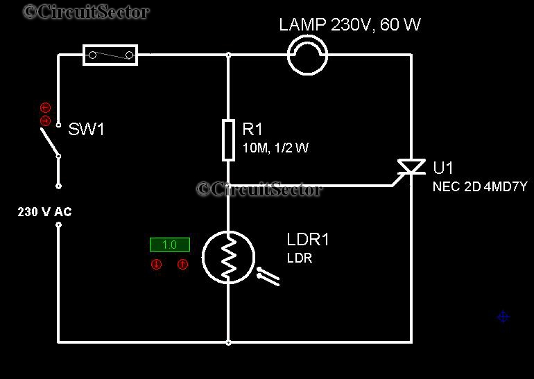
It is very convenient to automatically light a lamp in our absence during the evening when it gets dark. This automatic night lamp circuit can be utilized to illuminate staircase lights, porch lights, etc., automatically using a domestic power...
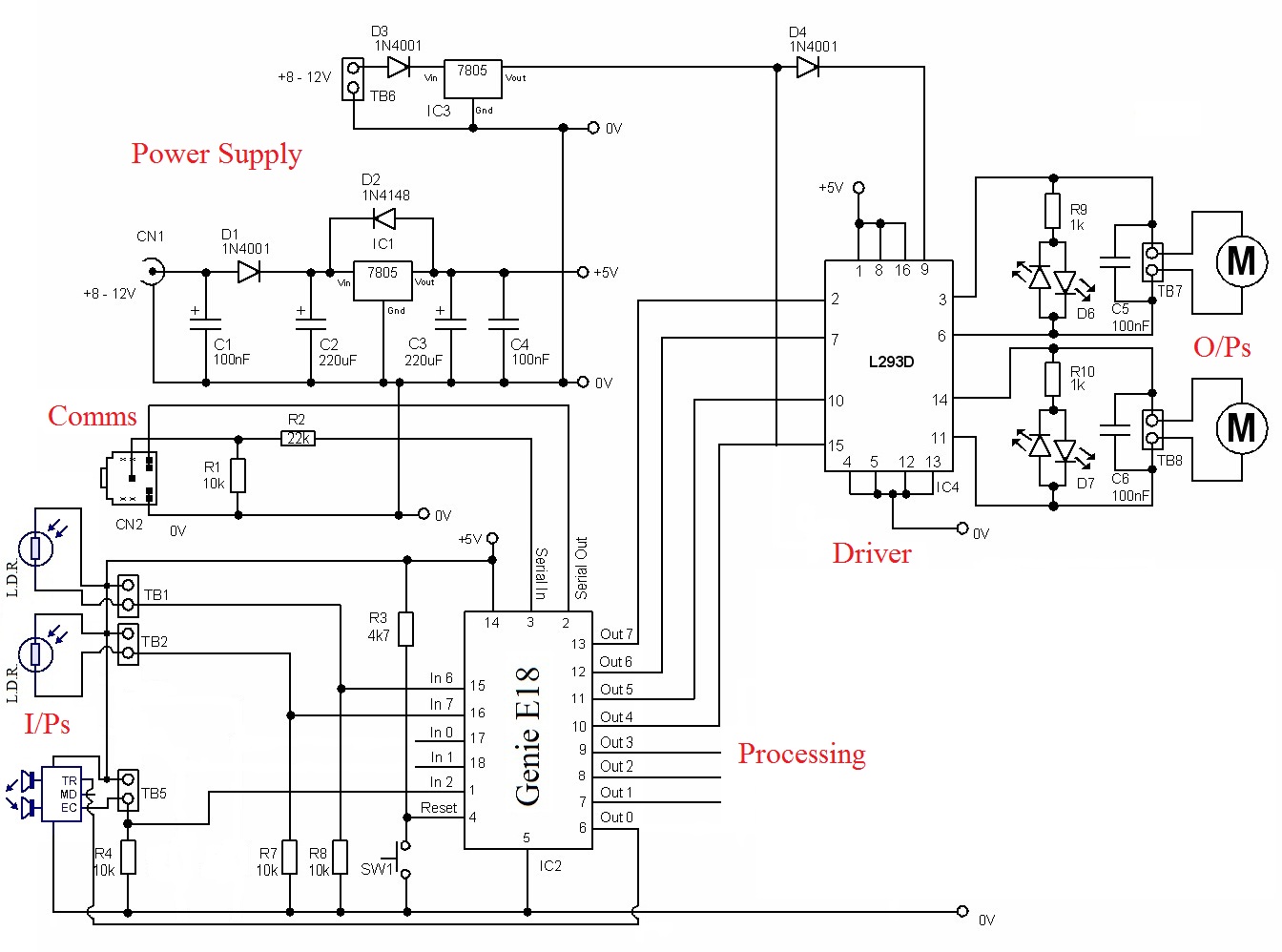
The circuit requires a power source to function. The PIC needs a 5-volt supply, while the driver demands a higher voltage to operate the motors. Inputs: The inputs come from three sensors. Two of these sensors are Light Dependent...
Warning: include(partials/cookie-banner.php): Failed to open stream: Permission denied in /var/www/html/nextgr/view-circuit.php on line 713
Warning: include(): Failed opening 'partials/cookie-banner.php' for inclusion (include_path='.:/usr/share/php') in /var/www/html/nextgr/view-circuit.php on line 713