
clap on/off switch circuit using pic10f222
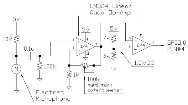
The Clap-Clap switch circuit is an innovative design that utilizes sound activation to control electronic devices. The primary components of this circuit typically include a microphone, an operational amplifier (op-amp), a microcontroller, and a relay or transistor to switch the load.
The microphone captures sound waves, specifically claps, and converts them into an electrical signal. This signal is then amplified using the op-amp, which enhances the signal strength to make it more suitable for processing. The amplified signal is fed into a microcontroller programmed to recognize the specific pattern of two consecutive claps.
Once the microcontroller detects the clap pattern, it sends a signal to activate a relay or transistor, which in turn switches the connected load on or off. The relay acts as an electronic switch, allowing for the control of higher voltage devices while keeping the low voltage components of the circuit safe.
To ensure proper functionality, it is essential to calibrate the microphone sensitivity and the timing within the microcontroller to accurately detect the clap sound without false triggers from background noise. Power supply considerations must also be made, ensuring that the circuit operates within the voltage and current ratings of the components used.
This Clap-Clap switch circuit is suitable for various applications, including home automation systems, where users can control lights or appliances simply by clapping, offering a convenient hands-free operation.How to make a Clap-Clap on / Clap-Clap Off switch circuit! Hi all! This instructable not only gives the reader the information needed to create a clap-clap.. 🔗 External reference
Related Circuits

The LM2002 / 2002A is an audio power amplifier integrated circuit. The LM2002A features high voltage protection, with a maximum instantaneous power supply voltage of up to 40V, and comes in a 5-pin single in-line plastic package. This integrated...
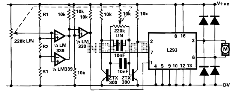
A limitation of the bi-directional proportional motor control circuit is that when the potentiometer is in its center position, the motor does not stop but continues to creep. This occurs due to the challenge of precisely adjusting the potentiometer...
This digital DIY tachometer for bicycles utilizes two reed switches to gather speed information. The reed switches are positioned near the wheel rim, where permanent magnets, attached to the wheel spokes, pass by and activate the switches. The speed...
The TEA5764UK is a single-chip, electronically tuned FM stereo radio that includes a Radio Data System (RDS) and Radio Broadcast Data System (RBDS) demodulator, along with an RDS/RBDS decoder. This device is designed for portable applications and features fully...
The following file contains detailed information about the design of a basic clock oscillator circuit diagram. Included in this file is information about selecting the components. The clock oscillator circuit is a fundamental component in various electronic systems, providing a...

Voltage variations and power cuts adversely affect various equipment such as TVs, VCRs, music systems, and refrigerators. This simple circuit will protect costly equipment from high and low voltages and voltage surges when power resumes. It also produces a...