
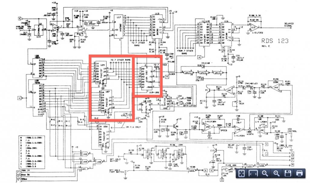
Circuit clarification needed

The circuit in question likely includes a voltage divider configuration, which is a fundamental concept in electronics used to produce a specific output voltage that is a fraction of the input voltage. A voltage divider consists of two resistors connected in series across a voltage source. The output voltage is taken from the junction of the two resistors.
In a typical voltage divider, the resistors R1 and R2 are connected in series. The total voltage (Vin) is applied across the series combination of R1 and R2. The output voltage (Vout) can be calculated using the formula:
Vout = Vin * (R2 / (R1 + R2))
This formula indicates that the output voltage is directly proportional to the resistance of R2 and inversely proportional to the total resistance of the series combination (R1 + R2).
The voltage divider is often used in applications such as sensor interfacing, where a specific voltage level is required for the input of a microcontroller or other devices. It is important to choose resistor values that provide the desired output voltage while ensuring that the load connected to the output does not significantly affect the voltage divider's performance.
When designing a voltage divider, one must also consider the power ratings of the resistors to prevent overheating, as well as the input impedance of the circuit that the voltage divider is connected to, as a low impedance load can alter the expected output voltage.Can someone please help explain to me how this circuit works? I am pretty sure I understand how the voltage divider network works. I am pretty sure I.. 🔗 External reference
Related Circuits
This motor speed controller utilizes a single IC, the LM1014, to regulate the speed of a DC motor. It detects the increase in motor current as the rotation of the motor increases. The motor speed controller is designed around the...
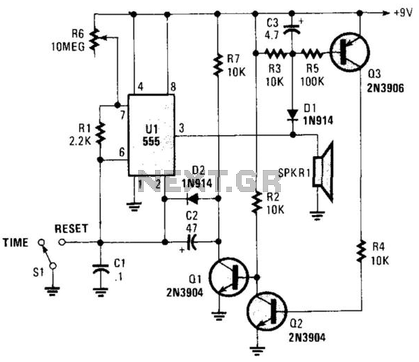
This circuit operates in astable mode and produces a tone at the end of the first period, which can last several minutes. When switch SI is in the time position, transistor Q3 is turned off because pin 3 of...
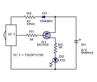
The cause may be dry solder joints, defective LEDs, or a flat battery (possibly due to a stuck key). The human eye cannot perceive infrared light, while a standard phototransistor such as the BP103 operates effectively in the infrared...
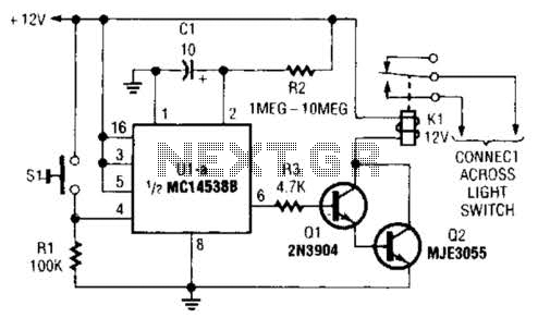
A normally open pushbutton switch (SI) provides a positive input pulse to pin 4 of U1, activating the integrated circuit (IC). The output from U1 at pin 6 delivers base-drive current to a Darlington pair consisting of Q1 and...
This project is suitable for individuals who enjoy experimenting with electronics. It presents a low risk of damaging the unit. This project involves creating a simple electronic circuit that allows users to engage in hands-on experimentation without significant risk. The...
One of the most notable RF amplifiers documented is Wes Hayward's post-mixer amplifier in the Progressive Communications Receiver. It is recognized as a highly effective high-level RF amplifier, operating with a standing current of 50 mA, which allows it...