
Lamp-Switching Circuit Circuit
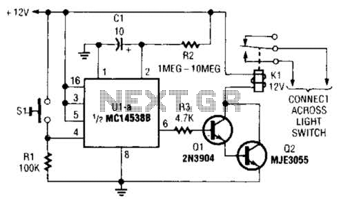
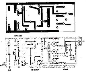
The circuit described utilizes a normally open pushbutton switch (SI) to initiate a timing sequence through an integrated circuit (IC) designated as U1. Upon pressing the switch, a positive pulse is sent to pin 4 of U1, which triggers the operation of the IC. The output at pin 6 of U1 is responsible for providing base-drive current to a Darlington pair formed by transistors Q1 and Q2. This configuration is advantageous for amplifying current, allowing for the control of larger loads like relays or motors.
The timing components of the circuit, which include a capacitor and a resistor, play a critical role in determining the duration for which the output remains active. The circuit design permits flexibility in selecting resistor values between 1 to 10 ohms, while the capacitor value can be adjusted to achieve the desired timing characteristics. This feature is particularly useful for applications requiring specific on durations.
For automotive applications, the circuit can be applied to control the headlights of a vehicle. By connecting the relay's normally open contacts across the existing headlight switch, the circuit allows the headlights to remain illuminated for a longer period upon pressing the pushbutton switch (SI). This is particularly useful for scenarios where the driver may need to keep the headlights on for an extended duration after exiting the vehicle.
In an alternative application for controlling an AC-operated lamp, the circuit can be integrated with the lamp's power switch. It is crucial to ensure that the AC power is turned off before making any connections to avoid electrical hazards. The relay contacts should be connected in parallel with the lamp's power switch contacts. This setup allows the pushbutton switch (SI) to control the lamp's operation, providing a convenient method for turning the lamp on and off with a timed delay.
Overall, this circuit design offers versatility in controlling various electrical loads while providing a simple user interface through the pushbutton switch. A normally open pushbutton switch (SI) delivers a positive input pulse to pin 4 of Ul, triggering the 1C into action. The output of Ul at pin 6 supplies base-drive current to a Darlington pair comprised of Q1 and Q2, activating .
10- capacitor and any resistor value of from 1 to 10 can be used as the timing components.To use the circuit on an auto`s headlights, connect the relay`s normally open contacts across the car`s headlight switch and press SI to extend the on time. In connecting the circuit to control an ac-operated lamp, turn off the ac power and connect the relay contacts in parallel with the lamp`s power switch contacts. 🔗 External reference
Related Circuits
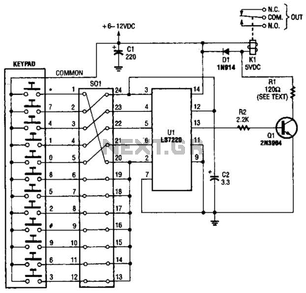
A block pinout diagram of the LS7220 keyless-lock IC is presented. The keypad must provide each key with a contact to a common connection. In this instance, the common connection is linked to the positive supply rail, allowing a...
There is a requirement for a compact flashlight to illuminate small text on integrated circuits (ICs) and provide better visibility when examining disassembled components. The flashlight should have a long battery life while avoiding excessive battery consumption, such as...
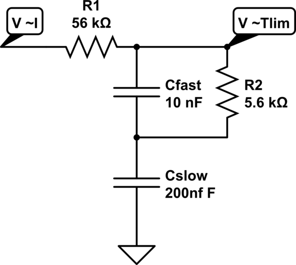
A MOSFET is employed to drive a load that includes a sense resistor in its current path. The voltage across this resistor is utilized to trigger a circuit capable of disconnecting the load in the event of an overcurrent...
The system primarily consists of a permanent magnet disk, an integrated Hall sensor, a strobe gate, time base signal circuits, a power counting circuit, and a digital display circuit. The counting and digital display circuit utilizes the CMOS-LED digital...
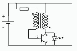
The power used for realignment is considered a loss in the context of the overall circuit. Due to the hysteresis loss in the saturable-core reactor, the power gain is relatively low. Adding a rectifier to the load circuit can...
When the door is opened, SW1 closes, powering the circuit and turning on the lamp. C1 begins to charge slowly through R1, and when the voltage at pins #2 and #6 of IC1 reaches 2/3 of the supply voltage,...