
Circuit RF Amplifier

The described RF amplifier circuit is integral to enhancing the performance of the Progressive Communications Receiver, particularly in environments with limited antenna options. The use of a post-mixer amplifier configuration allows for effective signal amplification while maintaining low distortion levels. The standing current of 50 mA ensures robust performance, enabling the circuit to handle strong incoming signals without compromising the integrity of the output.
In practical applications, the circuit's design accommodates various antenna configurations, including the Hamstick, which is particularly beneficial in urban settings where space and regulations limit antenna deployment. The amplifier's gain can be adjusted based on the specific antenna used, allowing for fine-tuning that maximizes reception quality. The option to bypass the RF amplifier in high-quality antenna systems provides flexibility, ensuring that the receiver can adapt to different operational conditions.
Furthermore, the implementation of a 3 dB Pi-Network Resistive Attenuator at the output stage enhances signal integrity by minimizing reflections and improving impedance matching. This adjustment is crucial in maintaining consistent performance across different frequency bands. The careful selection of additional components, such as an antenna tuner and counterpoise arrangements, further optimizes the receiver's functionality, ensuring that it can perform effectively even with non-ideal antennas.
Overall, the circuit exemplifies a well-thought-out design that prioritizes performance in challenging conditions, making it an essential tool for amateur radio operators seeking reliable communication capabilities.One of the best RF amplifiers ever published was Wes Hayward`s post mixer amplifier in the Progressive Communications Receiver. It quickly became known as a great high level RF amplifier. With a standing current of 50ma, it takes a very strong signal to upset this amplifier. Check out page 15. 24, figure 15. 33 of the 2000 ARRL Handbook for Radio Amateurs for more information. This receiver is designed to work in the worst conditions that many hams have to tolerate: living in a condo or townhouse with antenna restrictions. A Hamstick antenna mounted just inside a bedroom window (in a townhouse) was used to test the sensitivity of the receiver.
A 16-18dB RF amplifier was used to provide the necessary sensitivity to work with a hamstick in a townhouse/condo. When this receiver is used with better antennas, the front end gain needs to be "tuned" for the antenna system used.
The RF amplifier needs to be bypassed in really good antenna systems, and maybe used only on the 17 meter band. Instructions for bypassing the RF amplifier are near the bottom of this page. The right amount of gain is a compromise between sensitivity and dynamic range. When using a Hamstick, signal levels are so low that going all the way for sensitivity gives a very good performing setup.
An excellent article that shows the effectiveness of using Hamsticks in a dipole configuration is "Receiving Antennas", by Robert L. Nelson, K6ZGQ, Ham Radio, May 1970, pp 56-63 (Subtitled: "A discussion of special purpose antennas for receiving - including some novel ideas for improved performance on the lower bands").
Mr. Nelson states, from the article above (page 62), "I have obtained good results with both a helical dipole and an untuned five-foot-long dipole with a capacitive hat when worked through an antenna coupler. However, the helical arrangement is somewhat better. " Again, on the helical dipole (page 62), "This antenna, if mounted horizontally, will be horizontally polarized, electrical-field sensitive and balanced with respect to ground, and will discriminate rather well against local noise.
" Even though this receiver has plenty of gain to work with small antennas, they must be tuned and matched to the 50 ohm input of the receiver. An antenna tuner must be used with random wires for best results. A Hamstick used at its design frequency gives the best reception. However, a 17 meter Hamstick gives even reception throughout all the bands of this receiver. My ground lead was a #12 wire to the pipes in the bathroom. A counterpoise wire run along the baseboard of a room will also work as a ground. Other Hamsticks give different results. A 30 meter Hamstick will work on 17 meters, but on none of the others. A 20 meter Hamstick will work ok on 40 meters, but hardly at all on 30. A 40 meter Hamstick will not work very well on 20 meters, etc. For general listening, use a 17 meter hamstick. To gage proper gain at the RF stage, listen to the signal in the speaker and check for 455 kHz IF strip noise.
This receiver was designed so IF noise is masked by the signal levels entering the IF strip. If you do not get a definite rise in background noise when tuning a band with the bandpass filter pot, more amplification is needed. If the band noise blows you off the table, add more loss in the 50 ohm pad. A 3dB pad is installed at the output of the RF amplifier. Higher loss pads may be used. Tests on loss/gain through the front end and bandpass filters indicate the receiver has the same gain with or without the 3 dB pad.
The reason surmised is that the gain is improved by better matching with the 3dB pad versus a little mismatch that loses some signal strength without the pad. The 3dB pad is recommended in every situation. Real differences begin with a 6db pad. The 50 ohm pad used in the receiver is a Pi-Network Resistive Attenuator. The following are some values that would be useful in this receiver. Reference for th 🔗 External reference
Related Circuits

The preamplifier circuit is designed to offer appropriate loading for phono cartridges with reluctance. It achieves a gain of approximately 25 dB at 1 kHz (converting an input of 2.2 mV to an output of 100 mV). The circuit...
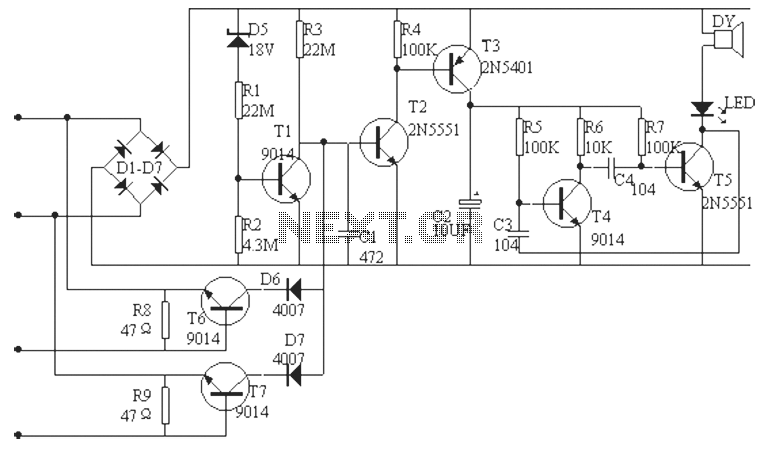
The phone alarm device is designed to monitor and prevent unauthorized use of a telephone line. When interference signals are detected on the line due to theft attempts, the alarm activates, preventing the thief from making calls while alerting...
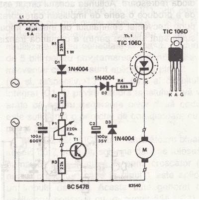
This AC drill speed controller circuit schematic allows for the control of the drilling speed of a borer or drilling machine. This project is based on the principle that... The AC drill speed controller circuit is designed to modulate the...
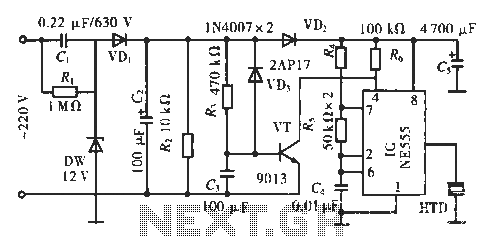
The circuit utilizes a 555 integrated circuit (IC). When an incoming call is received, 220 V AC is stepped down through resistor R1, followed by rectification using diode VD1. A voltage regulator (DW) is employed, and capacitor C2 is...
This circuit is designed to power a lamp or other appliance for a specified duration of 30 minutes, after which it automatically turns off. It is particularly useful for nighttime reading, as it can turn off a bedside lamp...
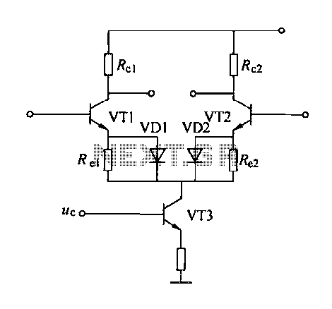
A controllable gain amplifier functions as an automatic gain control circuit within the execution unit. The primary methods for controlling the amplifier's gain involve two approaches: one is by adjusting certain parameters of the amplifier itself, such as emitter...