
LM1812 uses ultrasonic anti-collision circuit design
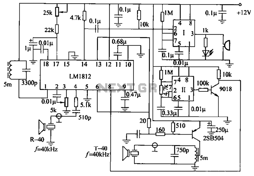
The ultrasonic anti-collision circuit operates on the principle of emitting ultrasonic waves and measuring the time taken for the echoes to return after bouncing off an object. The LM1812 circuit serves as the heart of this system, facilitating both the transmission of ultrasonic signals and the reception of their reflections. The circuit includes a potentiometer that allows users to set the desired detection range, typically between 2 to 3 meters, to suit specific applications.
The timebase circuit, which includes a one-shot timer, plays a crucial role in determining when to trigger the alarm. When the distance measurement indicates that an object has entered the preset alarm zone, the input pin of the timebase circuit receives a low signal, which corresponds to about 1/3 of the supply voltage (Vcc). This low signal activates the one-shot timer, causing its output pin to go high. The high output signal is then utilized to illuminate an LED and activate an electronic buzzer, providing both visual and audible alerts.
The T/R-40 series ultrasonic sensor is specifically designed for this type of application, offering reliable performance in detecting objects within the specified range. The circuit can be effectively mounted at the rear of a vehicle to prevent collisions while reversing, ensuring that the driver is alerted to any obstacles in the path. Furthermore, this circuit can be adapted for anti-theft purposes, where it can monitor entry points to a property. If an intruder approaches within the defined range, the system will trigger the alarm, enhancing security for residential, commercial, and financial environments. This versatility makes the ultrasonic anti-collision circuit a valuable tool in various safety and security applications. Circuit principle : ultrasonic anti-collision circuit is shown, when the LM1812 circuit by circuit group to control the transmission and reception of LM1812 (LM1812, ie send an d receive). Available Skfl distance control potentiometer to adjust, and can be controlled 2-3m. Timebase circuit consisting of one-shot circuit, when reaching the alarm distance, time-based circuit pin input low (equivalent to 1/3Vcc) 1, the one-shot circuit is triggered, pin output high. LED lights while electronic buzzer alarm. This circuit ultrasonic transmitting/receiving sensor is T/R-40 series, the circuit can be used for anti-collision car when reversing alarm, installed in the rear of the car can be.
Can also be used for anti-theft alarm, the thief entered the range of 2 ~ 3m, began to alarm for home, warehouse, finance and other departments.
Related Circuits
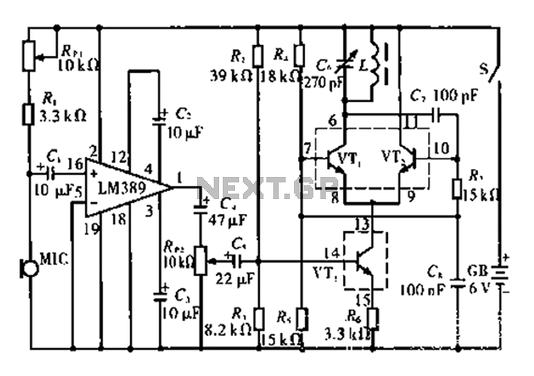
This circuit is tested and functional. The LM389 integrated circuit serves as the core element, where the voice channel number is acquired by the microphone (MIC) and converted into electrical signals. These signals are amplified by the volume control...
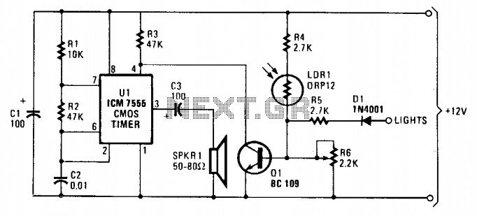
As dusk begins to fall, the sensor, which is a cadmium-sulfide light-dependent resistor (LDR), activates a small horn to provide an audible reminder to turn on the lights. The circuit can be turned off by simply switching on the...
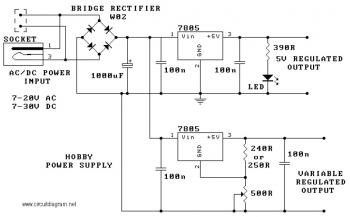
The circuit utilizes the 7805 voltage regulator, which features three connections: input, output, and ground. It delivers a fixed output voltage, with the last two digits of the part number indicating the specific output voltage, such as 05, 06,...
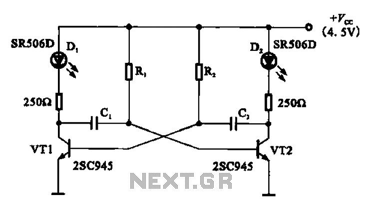
The multivibrator flashing light emitting diode (LED) display driver circuit can be utilized in toys, creating flashing effects in the eyes of animals or monsters. This circuit employs a multivibrator configuration, typically a 555 timer IC or a similar component,...
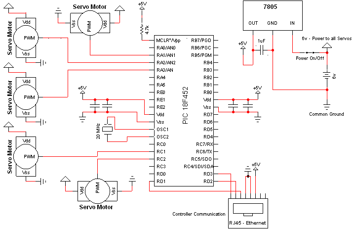
The hardware schematic for the robotic arm, referred to as the wooden menace, is quite straightforward. The PIC microcontroller has one control line connected to each servo and also connects to an RJ45 connector, which is used to receive...
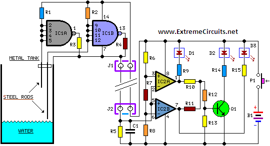
When the water level is below the steel rods, there is no contact between the metal can and the rods, which are supported by a small insulated wooden board. The circuit built around IC1 draws no current, resulting in...