
Circuit Crystal Oscillator/Amplifier
This oscillator circuit is designed to deliver high-frequency stability and low phase noise, making it suitable for applications requiring precise frequency generation. The use of inductive-mode crystals allows for flexibility in frequency selection, while the wideband post-amplifier ensures that the output meets the necessary power levels for subsequent stages in a communication system. The integration of LED indicators enhances usability by providing immediate visual feedback on the oscillator's operating state, which is particularly advantageous during troubleshooting. The careful design of the switching mechanism and the incorporation of capacitive elements for frequency tuning exemplify a thoughtful approach to balancing performance and reliability. Overall, the oscillator represents a significant advancement in low-noise frequency generation technology, suitable for both amateur and professional radio applications.This oscillator is a variation of the oscillator presented by Ulrich L. Rohde, DJ2LR, in his article "Evaluating Noise Sideband Performance in Oscillators", Ham Radio, October 1978, Page 51. The original circuit is at the bottom of the web page "4 MHz Oscillator" in the Super Receiver section of this web site.
The article states the above oscilla tor is a "suitable low-noise crystal oscillator circuit with a wideband postamplifier that delivers the required +17 dBm output level or slightly more. Any inductive-mode crystal between 400 KHz and 30 MHz can be plugged into this circuit and give useful output without any adjustments.
" "The noise performance of the crystal oscillator circuits. is better than 120 dB/Hz at 1 KHz from the carrier, and 150 dB/Hz or more at 20 KHz from the carrier. Because of their excellent noise performance, these circuits can be used as local oscillators without degrading receiver performance; very few oscillators and practically no frequency synthesizers achieve their low-noise sideband levels.
" Update: Email correspondence with Dr. Rohde (April 2008) shows that even better performance is now available. Dr. Rohde wrote that ". at 5 MHz my oscillator with a 2008 quality crystal, Q=2. 6 E6, Cs=8ff, and some modifications gives a superb phase noise. " See curve below, much better noise now. Diode switching is used to switch the crystal frequency. Regular LEDs were found to work just as well as 1N914s, used in almost every crystal switching circuit in Ham radio literature. The advantage of using LEDs is the visual indication of which oscillator is on, helping with diagnosis in case the switching circuit is not operating properly, or in the case of this receiver, ambient light is interfering with the proper operation of the phototransistor.
When the BPX38 (Q1) is off, no current flows through Q1, the 100K resistor (R2), brings the gate voltage of Q2 to zero, turning off Q2. B+ flows through a 1K resistor (R3), through the 3. 547 crystal LED (DS2), which brings the gate of Q3 to 12 volts, which turns on Q3. No current is flowing, since the Gate of Q3 is very high impedance, so the 3. 547 LED (DS2) is off. But Q3 is turned on, which supplies 12 Volts to the 4. 000 LED (DS1) through a 1K resistor (R1), which yields an oscillator frequency of 4. 000 MHz. If the 4. 000 MHz crystal filter is on, the IRED emitter at the filter shines infra-red light on the BPX38, which turns the phototransistor on.
The oscillator output is at 3. 547 MHz. When the BPX38 is on, the Gate of Q2 raises to 12 volts, turning on Q2. The source of Q2 grounded, so when Q2 is turned on, the Gate of Q3 is grounded, turning off Q3, which turns off the 4. 000 LED (DS1). This also grounds the cathode of the 3. 547 LED (DS2) and B+ flows through the 3. 547 MHz LED (DS2), turning on the oscillator to 3. 547 MHz. When the kit LEDs (bright reds) are used in this circuit, there are no problems with the switching circuit.
But if the LEDs are modified, a 100K resistor needs to be added to the gate of the bottom IRFU220 (One closest to the 12 Volt box near the row of holes. ). This resistor goes to the gate of the IFFU220 and to the 12 Volt box. Put one lead in the middle hole of the 12 Volt box and then solder the other end to the gate lead of the IRFU220 underneath the board.
See the schematic above. The 200pf capacitors between the LEDs and the crystals keep DC current from getting into the crystals, and provide tuning of the crystal frequency so that switching between the crystal filters gives approximately the same BFO note in the output of the receiver. An optional trim cap is provided on the 4. 000MHz crystal to future refine the crystal frequency. Changing the 200pf caps to other values is no problem, but do not remove the capacitors and replace them with a wire, for the oscillator may not work, or crystal damage may occur.
The four unlabeled holes on the far left hand side of the 🔗 External reference
Related Circuits
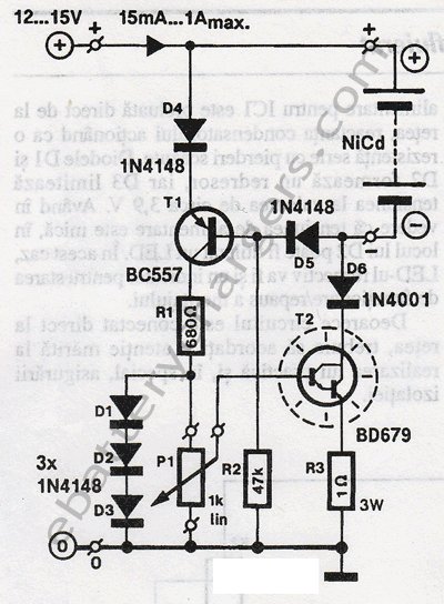
This 24V to 36V linear battery charger is long overdue. While this is an old circuit technique, it is optimized for charging higher voltage lead-acid batteries. The 24V to 36V linear battery charger is designed to provide a stable charging...
A continuously running cooling fan can be a significant nuisance and is not essential for most instruments. The 12V smart fan control presented here allows the fan to operate only when necessary. The 12V smart fan control circuit is designed...
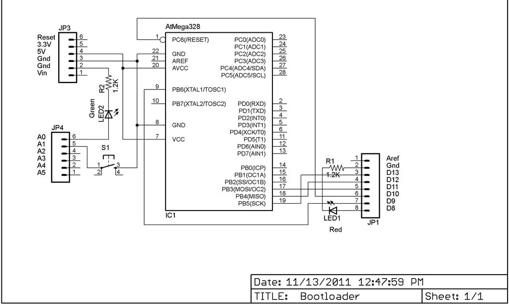
This Lazy Old Geek is also an Arduino enthusiast. One of the common microcontrollers used by Arduinos is the Atmega328 chip. To utilize Arduino software, the Atmega must be equipped with bootloader software. There is a notable difference between...
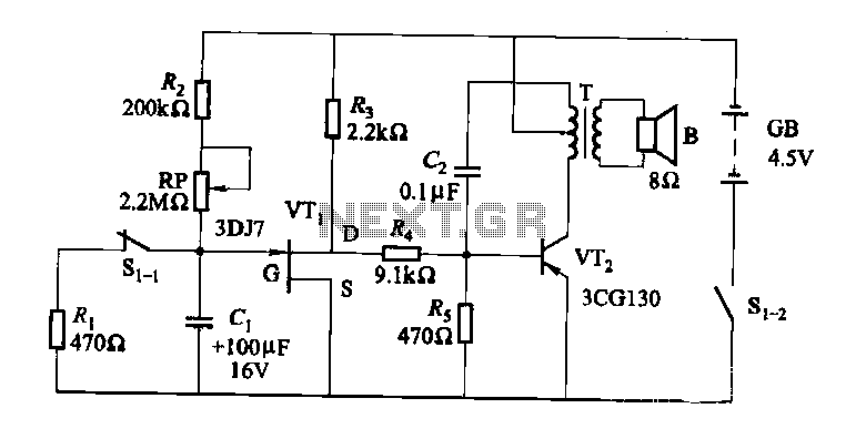
The darkroom circuit is designed for one-time exposure and emits an audible signal when the developing time is reached. This circuit can be utilized for photofinishing large timers and other applications. It comprises components such as FET VTi, resistors,...
A computerized infrared remote project is a simple device designed for recording and playing back streams of infrared data, specifically the codes transmitted by remote controls. Software is provided for use in both DOS and Windows environments, along with...
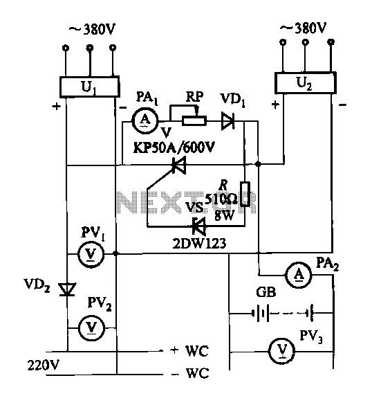
The DC panel battery is commonly utilized in power plants and substations within DC systems. To enhance the safety and reliability of the current system, an uninterrupted power supply switching circuit may be implemented. This circuit includes components such...