
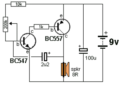
Ticking Bomb circuit diagram
Additionally, there is a heat detector circuit integrated with a siren output, utilizing a complementary pair of NPN (BC109) and PNP (AC188) transistors to detect heat, such as from a fire, and activate an alarm. The HT2884 IC generates various sound effects, including two laser gun sounds, a dual-tone horn, two bomb sounds, two machine gun sounds, and a rifle shot sound. The circuit operates on a 3V battery, with the IC capable of functioning at various voltages.
Another mentioned circuit is an electronic horn based on the LM3900 quad op-amp IC, which features four independent operational amplifiers capable of a wide output voltage swing and functioning up to 32V DC. Furthermore, a three-stage FM transmitter circuit is described, capable of transmitting over a distance of up to 1 kilometer in open conditions, using RF transistors and BC547s in its design. Lastly, the sound-activated light circuit employs a condenser microphone to capture sound, generating AC signals that are processed through a DC blocking capacitor to amplify the signals using BC549 and BC547 transistors, delivering current pulses from the collector.
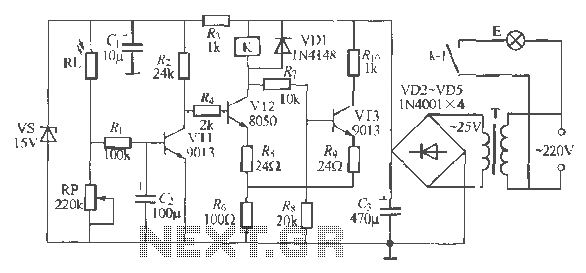
The ticking bomb sound generator circuit is designed to produce a sound resembling a loud ticking clock. The operation begins with the charging of a 2.2 µF capacitor. Once the voltage at the base of the NPN transistor exceeds 0.65 V, the transistor activates, which subsequently triggers the BC557 transistor. This action results in an increase in voltage at the collector, effectively transferring the charge from the 2.2 µF capacitor into the base of the BC547 transistor, thereby enhancing its conduction.
The frequency of the ticking sound can be adjusted using a 220 kΩ potentiometer, allowing for variations in the sound output. This feature adds versatility to the circuit, enabling users to customize the ticking sound to their preference.
In addition to the ticking bomb sound generator, a heat detection circuit is integrated with a siren output. This circuit utilizes a complementary transistor pair consisting of an NPN BC109 and a PNP AC188 transistor to detect heat, which may indicate a fire. When heat is detected, the circuit activates an alarm or siren, providing a crucial safety feature.
The HT2884 integrated circuit is responsible for generating various sound effects within the system. It is capable of producing eight distinct sounds, including two laser gun sounds, a dual-tone horn, two bomb sounds, two machine gun sounds, and a rifle shot sound. This versatility makes the circuit suitable for applications requiring diverse audio signals.
The circuit operates on a 3V battery, although the HT2884 IC is designed to function across a range of voltages, enhancing its compatibility with different power sources.
Another circuit of interest is an electronic horn constructed using the LM3900 quad op-amp IC. This circuit features four independent operational amplifiers, each capable of delivering a substantial output voltage swing. The LM3900 can operate at voltages up to 32V DC, making it suitable for a variety of applications.
Furthermore, a powerful three-stage FM transmitter circuit is described, which can achieve a transmission range of up to 1 kilometer in open areas. The transmitter employs an RF transistor in its output stage, along with two BC547 transistors for the initial stages of amplification. The effective range of the transmitter is influenced by environmental conditions, such as whether it is used indoors or outdoors.
Lastly, the sound-activated light circuit utilizes a condenser microphone positioned to capture sound waves effectively. The microphone generates AC signals that are passed through a DC blocking capacitor to the base of a BC549 transistor. This transistor, along with a second transistor (BC547), amplifies the sound signals, producing current pulses at the collector that can be used to activate a light source. This design demonstrates the integration of audio sensing and lighting control in a single circuit.Ticking Bomb sound generator circuit diagram. The circuit gets going by charging the 2. 2uF and when 0. 65v is on the base of the NPN transistor, it begins to turn on. This activates the BC557 and the voltage on the collector increases. This forces the small charge on the 2. 2uF into the base of the BC547 to turn it on more. Here the low cost and eas y build circuit of ticking bomb sound generator. This circuit generates a sound matching to a loud clicking clock. The frequency of the tick is altered through the 220k potensiometer part. The circuit gets going by charging the 2. 2uF and when 0. 65v is on the base of the NPN transistor, . This is the diagram of heat detector circuit which already integrated with siren circuit in the output. This circuit applies a complementary pair comprising NPN metallic transistor T1 (BC109) and PNP germanium transistor T2 (AC188) to detect heat (because of outbreak of fire, for example) in the area and activate a siren/alarm.
The collector of. All sounds in this circuit are generated by HT2884. There are 8 different sound effect can be produced that are 2 lazer guns, 1 dual tone horn sound, 2 bomb sounds, 2 machine gun sounds and a rifle shot sound. Note: Power is a 3 Volt battery, but the IC will work with any voltage. This is an easy, low cost and easy built circuit of an electronic horn which is designed close to quadruple op-amp IC LM3900 (IC1).
IC LM3900 has four independent operational-amplifiers (A1 through A4) having a large output voltage swing. It is able to operate at up to 32V DC. The 1st op-amp (A1) is designed. This circuit is a powerful three stage, 9V FM transmitter (Tx) with a range of up to 1 kilometer in the open.
It uses an RF transistor in its output stage and two BC547`s for the first two stages. Distance of trans-mission is critically dependent on the operating Conditions (in a building or out on. How this sound activated light works: The condenser microphone fitted inside a position to catch the sound and generates AC signals, which pass by means of DC blocking capacitor C1 for the base of transistor BC549 (T1).
Transistor T1 as well as transistor T2 amplifies the sound signals and delivers current pulses within the collector. 🔗 External reference
Related Circuits
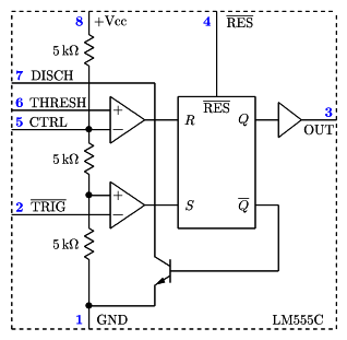
It is a typical Astable Multivibrator (AMV) setup. The capacitor charges through both resistors until it reaches 2/3 of Vcc, which is the level of the internal comparator. This triggers a flip-flop, activating the Discharge output (DIS). The capacitor...

This circuit resembles an LED clock but utilizes 12 neon indicator lamps in place of LEDs. It operates on two high-capacity nickel-cadmium cells (2.5 volts), providing power for several weeks. A small switching power supply generates the high voltage...
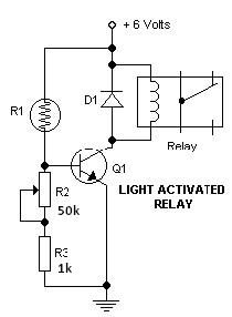
This light-dark switch activated relay circuit schematic represents one of the simplest electronic circuits designed to activate other electronic devices based on light or darkness. It requires a single electronic relay and a few common components that are not...
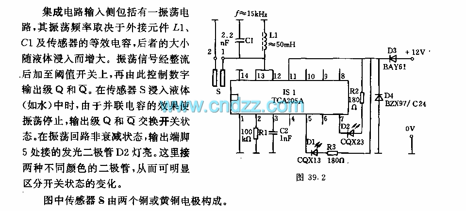
The integrated circuit input side contains an oscillating circuit, where the oscillation frequency is determined by the external components L1, C1, and the sensor's equivalent capacitance. The equivalent capacitance increases as the sensor is immersed in liquid. The oscillating...
The circuit operates as a light-activated switch that controls white moving lights. It features high sensitivity, stable performance, and good anti-interference characteristics. A photosensitive resistor (RI) is employed to detect ambient light levels. During the day, the resistor exhibits...
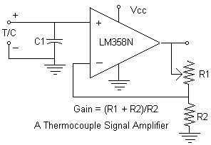
Continuing with the thermocouple interface concept, the next step is to amplify the TC's millivolt signal into a more readable analog voltage, on the order of 0 to 5VDC. This simple circuit fits the bill. The LM358N is a...