
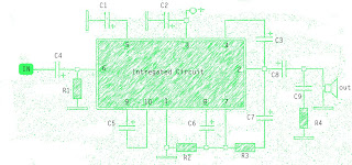
Circuit Diagram Of Alarm Power Supply
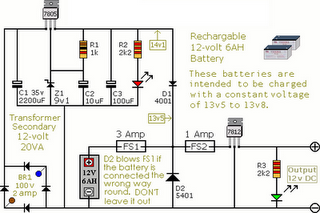
The Alarm Power Supply Circuit is designed to provide a stable and reliable power source for a Modular Burglar Alarm system. The circuit typically consists of a transformer, rectifier, voltage regulator, and filtering components. The transformer steps down the mains voltage to a lower AC voltage, which is then rectified by a diode bridge to convert the AC voltage into pulsating DC.
The voltage regulator ensures that the output voltage remains constant at 12 volts, despite variations in input voltage or load conditions. Capacitors are employed for filtering to smooth out the pulsating DC, reducing ripple and providing a cleaner power supply to the alarm system.
The circuit is rated for a current output of 1 amp, making it suitable for powering various components of the burglar alarm, such as sensors, sirens, and control panels. Protection features such as fuses or circuit breakers may also be included to safeguard against overcurrent conditions.
Overall, this power supply circuit is essential for ensuring the proper functioning of a Modular Burglar Alarm, providing the necessary voltage and current while maintaining reliability and safety.The following circuit shows about Alarm Power Supply Circuit Diagram. Features: 1-amp current, suitable for the Modular Burglar Alarm, 12-volts .. 🔗 External reference
Related Circuits
The current generated flows through clips placed on the earlobes. The output current is adjustable from 80 to 600 microamperes, following the recent launch in Europe. The described device utilizes a current generation mechanism that delivers a controlled microcurrent through...
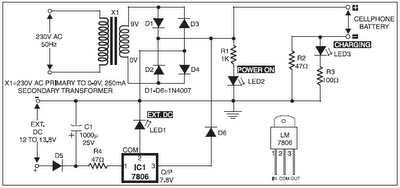
The 220V AC mains supply is downconverted to 9V AC by transformer X1. The transformer output is rectified by diodes D1 through D4 wired in bridge configuration, and the positive DC supply is directly connected to the charger's output...

A flashing LED indicates the need to water a plant in a 3V powered circuit. This circuit is designed to signal when a plant requires water. A LED flashes at a specified interval. This circuit operates on a 3V power...

These do-it-yourself FM transmitters are relatively simple to construct and provide a satisfying experience when music is played through the radio receiver. Comments and links to additional designs that are not included in the best list are welcome. FM transmitters...
It is possible to apply switch-mode techniques to a silicon CMOS semiconductor process to create a current-mode power amplifier with high gain and efficiency for use in 2.4-GHz wireless applications. Amplification at 2.4 GHz is essential for various wireless...
The amplifier circuit is well-suited for use in subwoofer speakers due to its robust performance. This circuit utilizes an integrated circuit (IC) based on the STK series. It can be employed in vehicles equipped with speakers or a subwoofer...
Warning: include(partials/cookie-banner.php): Failed to open stream: Permission denied in /var/www/html/nextgr/view-circuit.php on line 713
Warning: include(): Failed opening 'partials/cookie-banner.php' for inclusion (include_path='.:/usr/share/php') in /var/www/html/nextgr/view-circuit.php on line 713