
mobile phone battery charger circuit
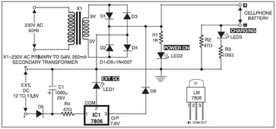
The circuit begins with a transformer (X1) that steps down the 220V AC mains voltage to a safer 9V AC level. The output from the transformer is then fed into a bridge rectifier configuration made up of four diodes (D1-D4), which converts the AC voltage to pulsating DC. The positive output from this rectifier is connected directly to the output terminal of the charger, while the negative output is routed through a current limiting resistor (R2) to ensure safe operation and prevent excessive current flow.
LED2 is incorporated into the design as a power indicator, illuminated when the circuit is powered. Resistor R1 is connected in series with LED2 to limit the current flowing through it, thereby protecting the LED from excess current. Additionally, LED3 serves as an indicator for the charging status. When the charger is in operation, the voltage drop across R2 (approximately 3 volts) activates LED3 through an additional current-limiting resistor (R3).
For versatility, the circuit can also utilize an external 12V DC supply. In this case, a polarity protection diode (D5) is used to prevent damage from incorrect connections. Resistor R4 is positioned after D5 to limit the current from the external supply, ensuring that it remains within safe operating limits.
The heart of the circuit is the LM7806 voltage regulator (IC1), which is designed to provide a steady output voltage of 7.8V DC. This output voltage is achieved by connecting LED1 between the common terminal (pin 2) of IC1 and the ground rail, which effectively raises the output voltage to the required level. LED1 also functions as an indicator for the presence of the external DC supply.
Once the circuit is assembled on a veroboard, it is advisable to enclose it in a suitable cabinet to protect the components and ensure safety during operation. A small heat sink is recommended for the LM7806 to dissipate any heat generated during operation, maintaining the regulator's efficiency and reliability. Proper attention to layout and component placement on the veroboard will enhance the performance and longevity of the circuit.The 220V AC mains supply is downconverted to 9V AC by transformer X1. The transformer output is rectified by diodes D1 through D4 wired in bridge configuration and the positive DC supply is directly connected to the charger`s output contact, while the negative terminal is connected through current limiting resistor R2. LED2 works as a power indica tor with resistor R1 serving as the current limiter and LED3 indicates the charging status. During the charging period, about 3 volts drop occurs across resistor R2, which turns on LED3 through resistor R3. An external 12V DC supply sourcecan also be used to energise the charger, where resistor R4, after polarity protection diode D5, limits the input current to a safe value.
The 3-terminal positive voltage regulator LM7806 (IC1) provides a constant voltage output of 7. 8V DC since LED1 connected between the common terminal (pin 2) and ground rail of IC1 raises the output voltage to 7. 8V DC. LED1 also serves as a power indicator for the external DC supply. After constructing the circuit on a veroboard, enclose it in a suitable cabinet. A small heat sink is recommended for IC1. 🔗 External reference
Related Circuits

This adjustable analog timer circuit begins timing when it is activated. A green LED illuminates to indicate that the timing is in progress. Upon completion of the set time period, the green LED turns off, a red LED activates,...
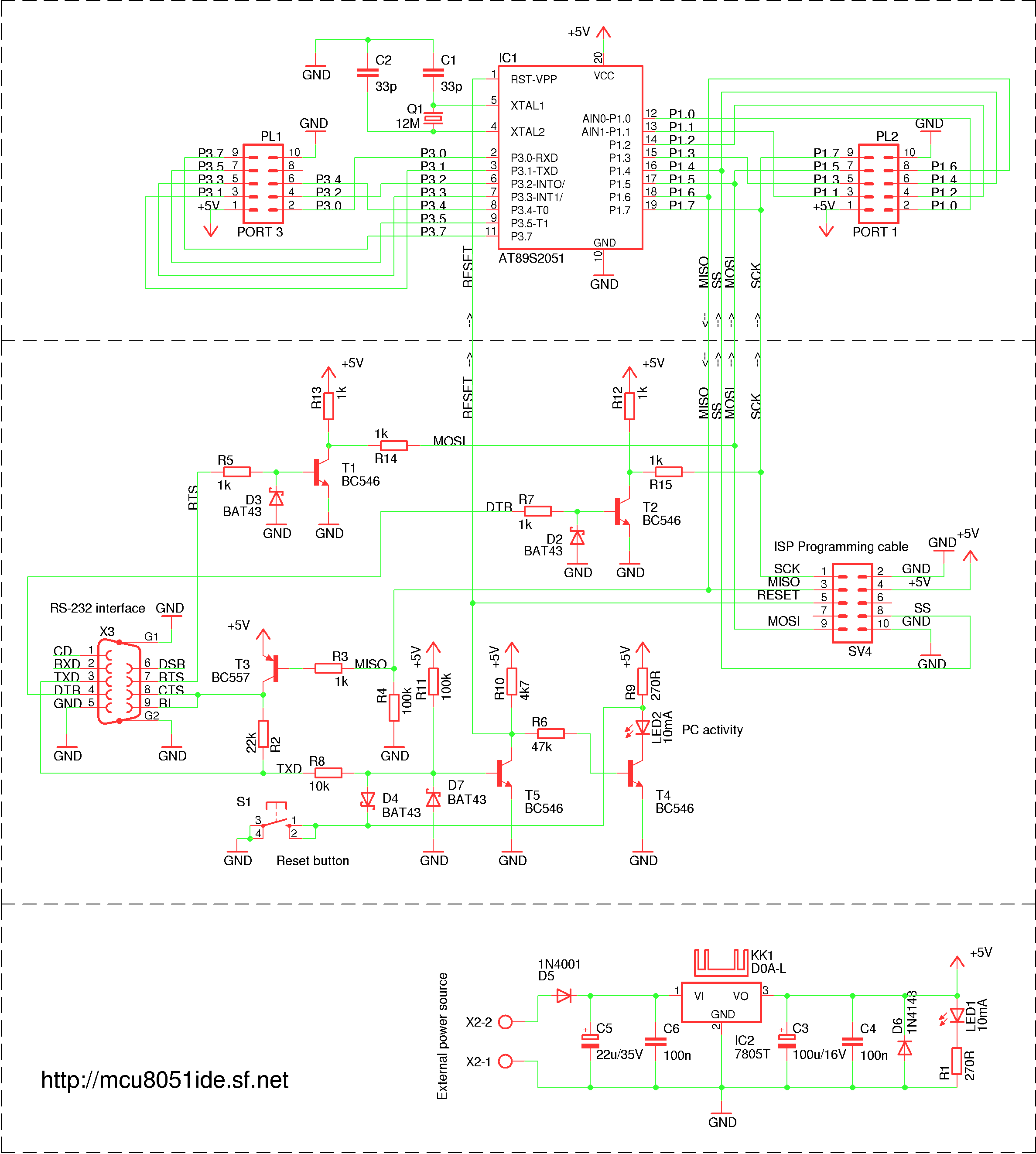
A simple RS-232 ISP programmer designed for AT89Sx devices, intended for educational purposes and hobbyist use. It has been tested with the AT89S2051 and AT89S8253 microcontrollers, utilizing a USB to serial port converter cable equipped with a PL2303 chip....
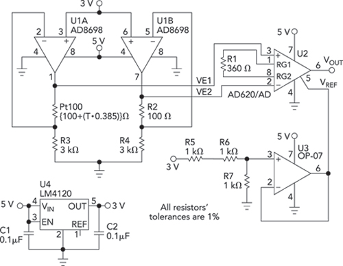
Bridge circuits are widely used for conditioning signals from resistive sensors. These circuits are sensitive to minor changes in resistance, providing a differential output from a single current or voltage source. However, the sensors connected to a passive bridge...
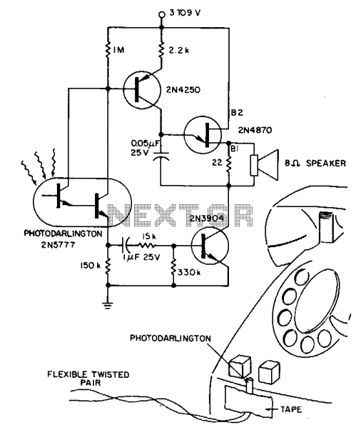
A 2N5777 photo-Darlington cell detects blinking light from transparent plastic buttons. A high-gain 2N3904 transistor is used to switch the power ON and OFF. The circuit can remain continuously connected to a 9 V battery, drawing less than a...

The following circuit is an example of how to get power from an RS-232 serial port. It provides regulated +5V power for logic circuits and also unregulated positive and negative power supplies for the RS-232 transmitting circuit. The circuit...
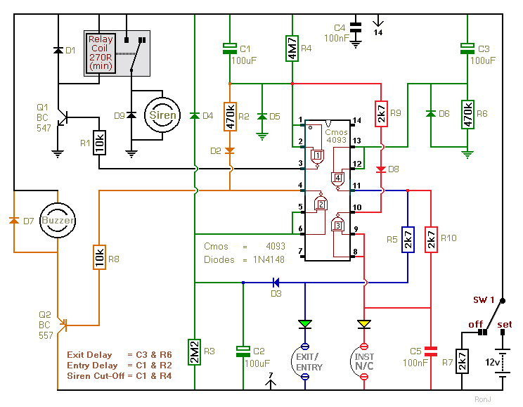
This two-zone alarm features automatic exit, entry, and siren cut-off timers. It was designed for the Beginner's Guide to CMOS Timers, providing a particularly detailed circuit description. An optional One-Time-Only module is available, which will deactivate the siren after...