
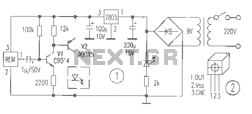
Circuit Diagram of Fan Speed Control With NE5560 IC
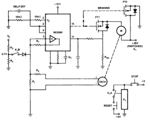
The circuit for a constant speed motor control typically employs feedback mechanisms to maintain a stable output speed. This can be achieved using a closed-loop control system, which includes components such as a microcontroller, sensors, and a driver circuit.
The microcontroller serves as the central processing unit, receiving input from sensors that monitor the motor's speed and load conditions. Commonly used sensors include tachometers or encoders, which provide real-time data on the motor's rotational speed.
The driver circuit, often consisting of a MOSFET or an H-bridge, regulates the power supplied to the motor based on the microcontroller's commands. This allows for precise adjustments to the voltage and current supplied to the motor, compensating for any changes in load or supply voltage.
Additionally, the use of PID (Proportional-Integral-Derivative) control algorithms can enhance the performance of the system. The PID controller calculates the error between the desired speed and the actual speed, adjusting the output to minimize this error over time.
Incorporating these elements into the design results in a robust motor control system capable of maintaining a consistent speed under varying operational conditions, thereby improving the overall efficiency and reliability of motor-driven applications.useful to make a constant speed motor control. Which means the speed will stay constant despite of load and electric voltage change. Component: . 🔗 External reference
Related Circuits
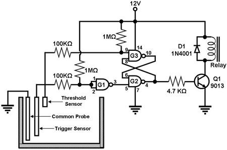
Figure 1 illustrates a circuit designed to monitor the water level in a tank and control a water pump accordingly. The primary component of the circuit is the CD-4011 Quad NAND gate, with three of its gates utilized as...

This project entitled Remote Control Through Internet allows us to monitor, control and automate our home from remote locations. In existing system home automation and security are separate systems working independently. Also in existing system if any one of...
Introduction The MIC2290 is an internally compensated standard step-up switching regulator that features an integrated power switch and Schottky diode. The inclusion of these components makes the MIC2290 an optimal solution for 48V Avalanche Photo Diode (APD) applications. In...
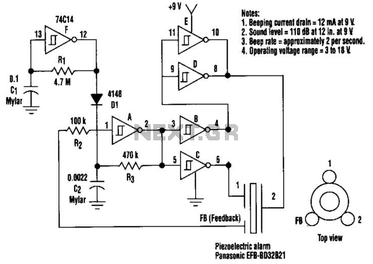
This circuit generates a loud sound of 110 dB using a 9 V power supply. It incorporates a single 74C14 (CD40106B) CMOS hex inverting Schmitt-trigger IC, which is utilized with a piezoelectric device that includes a feedback terminal. The...
The receiver provides two TV signals, one for the living room and another for the bedroom, along with a satellite receiver. Watching television in the bedroom is convenient in Taiwan; however, when watching television in the living room, it...
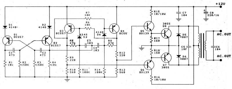
This circuit is a 100W DC inverter based on a transistored multivibrator and serves as a transistor signal amplifier. The inverter converts a 12V DC input voltage to approximately 220V AC. It is recommended to use a 12V car...