
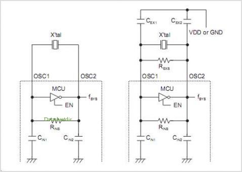
Mcu Reset And Oscillator Circuits Applicationnote
The MIC2290 is designed to efficiently convert a lower input voltage to a higher output voltage, making it suitable for applications requiring specific voltage levels, such as those involving 48V Avalanche Photo Diodes (APDs). The integrated power switch and Schottky diode minimize external component requirements, enhancing reliability and reducing board space.
The operation of the MIC2290 can be understood through its two-phase switching mechanism. During Phase 1, the internal NPN transistor acts as a switch, allowing current to flow into the inductor L1. This current generates a magnetic field, and energy is stored in the inductor as the voltage across it rises. The inductor is charged until the switch turns off, which is controlled by the feedback mechanism within the regulator to maintain the desired output voltage.
In Phase 2, the energy stored in the inductor is released to the output. When the switch turns off, the magnetic field collapses, inducing a voltage that adds to the input voltage, resulting in a higher output voltage. The Schottky diode provides a path for the current to flow to the output capacitor, ensuring that the output voltage remains stable and ripple-free.
The MIC2290's ability to work with compact 0603 inductors allows for a significant reduction in the overall size of the circuit, making it ideal for applications where space is at a premium. The design considerations for the MIC2290 include careful selection of inductor values and output capacitors to optimize performance and efficiency. The circuit's layout must also be considered to minimize inductive and capacitive parasitics, which can adversely affect the performance of the switching regulator.
Overall, the MIC2290 offers a robust solution for high-voltage applications, providing efficient power conversion and a compact design suitable for modern electronic devices.Introduction The MIC2290 is an internally compensated standard step- up Switching Regulator with an integrated power Switch and Schottky Diode The attribute of an internal power Switch and Schottky Diode makes the MIC2290 the most optimized solution for 48V Avalanche Photo Diode (APD) applications. In addition to the critical integrated components , the MIC2290 CAN be used with 0603 size chip inductors when configured for 48V APD applications. The physically small inductor size comprised with the MIC2290 capabilities produces a very space optimized design. Theory of Operation Understanding how the MIC2290 APD application circuit works is similar to how a standard Step-up switching Regulator works.
The same analytical methods CAN be employed when modeling the behavior of the APD application circuit. The simplified MIC2290 APD application circuit is in Figure 2. The MIC2290 APD circuit works in two phases. The first phase, or Phase 1, increases the energy stored in the magnetic flux of the inductor (L1). This is accomplished with the internal power Switch (NPNx) turning on and allowing the inductor to experience a constant voltage from the input voltage (VIN) to ground.
Phase 1 is illustrated in Figure 3. Upon the second phase, or Phase 2, the energy stored in the 🔗 External reference
Related Circuits
The HV732 is a complete, high-speed, high-voltage ultrasound transmitter pulser. This high-performance CMOS integrated circuit (IC) is housed in a single 7x7x0.9 mm 44-lead multi-die QFN package. The HV732 can deliver up to ±2A source and sink current to...
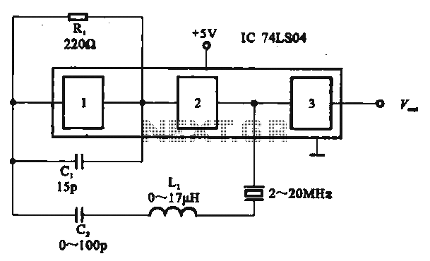
The circuit includes several gates arranged as a crystal oscillator circuit. Figure (A) illustrates a crystal oscillator circuit operating at 1 MHz, while Figure (B) depicts a 20 MHz crystal oscillator circuit. Figure (C) represents a variable crystal oscillator...
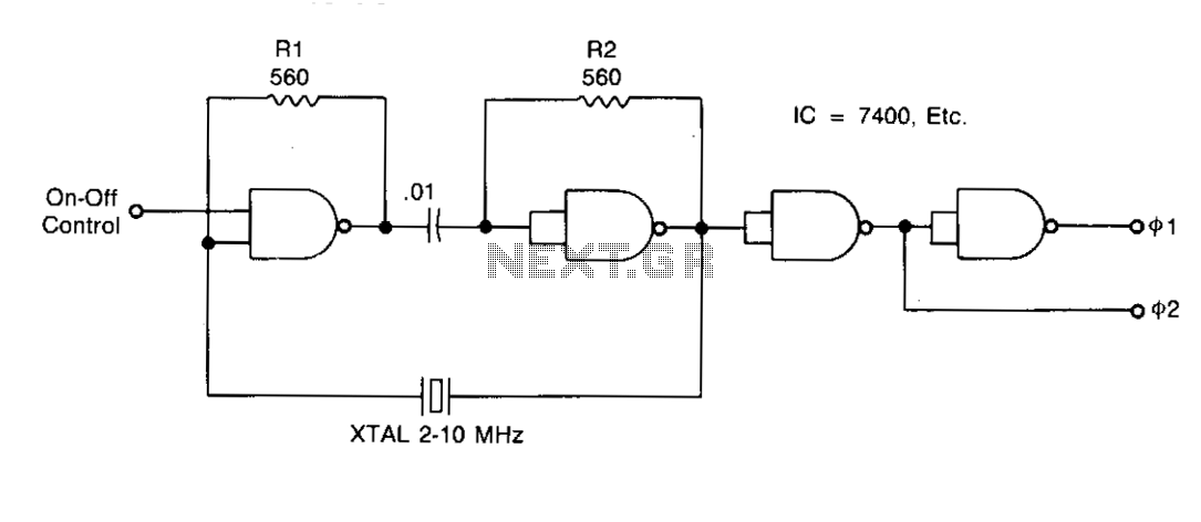
Resistors R1 and R2 stabilize the temperature of the NAND gates and ensure that the gates operate within a linear region during startup. Capacitor C1 acts as a DC block and must have an impedance lower than Vw at...
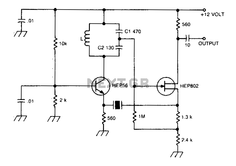
A typical Butler oscillator operating within the frequency range of 20 to 100 MHz incorporates a Field Effect Transistor (FET) in the second stage of its configuration. The circuit exhibits reliability issues when utilizing two bipolar transistors. In some...
This is a Voltage Controlled Oscillator (VCO) circuit. This circuit is based on a Hartley oscillator. The frequency depends on the values of C1 and L1. The Voltage Controlled Oscillator (VCO) circuit described operates using a Hartley oscillator configuration, which...
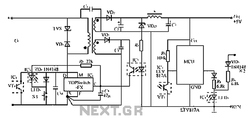
The circuit diagram of the TOPSwitch FZ chip switching power supply is controlled by microcontrollers (MCUs). The microcontroller can be utilized with inkjet printers, laser printers, and other computer peripherals. The TOPSwitch FX, which constitutes the switching power supply...
Warning: include(partials/cookie-banner.php): Failed to open stream: Permission denied in /var/www/html/nextgr/view-circuit.php on line 713
Warning: include(): Failed opening 'partials/cookie-banner.php' for inclusion (include_path='.:/usr/share/php') in /var/www/html/nextgr/view-circuit.php on line 713