
water level sensor circuit
The circuit operates based on a feedback mechanism that ensures the water level is maintained within specified limits. The CD-4011 Quad NAND gate is central to the operation, providing both logic functions and state retention through the flip-flop configuration. The use of simple conductive materials for the level sensors minimizes cost and complexity while ensuring reliable operation. The pull-up resistor connected to G1's inputs ensures that the circuit remains stable in the absence of water, preventing false triggering of the pump.
The RS flip-flop configuration, composed of gates G2 and G3, allows for the retention of state information regarding the water level. When the tank is empty, G1's output being low keeps G2 in a high state, which activates the pump through Q1. As the water level rises, the grounding of G1's inputs ensures that the pump continues to operate until the designated high water level is reached. At this point, the transition of G3's output to high effectively changes the state of G2, turning off the pump.
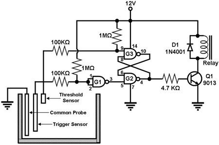
This circuit design is efficient for automatic water level control, reducing the need for manual intervention and preventing overflow or dry running of the pump. The simplicity of the components used, combined with the effective logic gate configuration, makes this circuit an excellent solution for water management in various applications.Figure 1 shows a circuit for sensing the water level in a tank and turning on or off a water pump accordingly. The main component of the circuit is the CD-4011 Quad NAND gate, three gates of which are used as shown in Figure 1 (gates G1, G2, and G3).
G1 is configured as an inverter (both inputs are shorted), while G2 and G3 form an RS flip-flop. T he level sensors are just copper or stainless steel wires. When there is no water in the tank, the trigger sensor is floating and the inputs to G1 are pulled `high` by their pull-up resistor, causing the output of G1 to be `low`. This, in turn, causes the output of G2 to be high, turning on Q1 which energizes the relay that powers up the water pump.
At this point, both of G3`s inputs are high, so its output is low. The water in the tank rises until it reaches the trigger sensor, which `grounds` G1`s inputs, causing G1`s output to go `high`. This does not affect the output of G2, though, since G2`s other input (coming from G3) is still `low`.
Thus, at this point, the water pump keeps on filling the tank with water. When the water level reaches the threshold sensor, G3`s pin 9 input is pulled `low`, causing the output of G3 to go `high`. This means that both of G2`s inputs are now `high`, causing G2`s output to go `low`. This turns off Q1, de-energizing the relay and shutting off the water pump. When the water level goes below the trigger sensor, G1`s inputs are pulled `high` again, causing G1`s output to go `low`.
This turns on the water pump and the cycle starts all over again. 🔗 External reference
Related Circuits
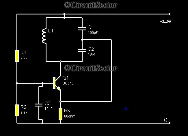
Metal detectors are typically complex devices that often incorporate expensive components, making DIY metal detector circuits uncommon. However, this metal detector hobby circuit can be built using only a few components, such as a BC548 transistor and a standard...
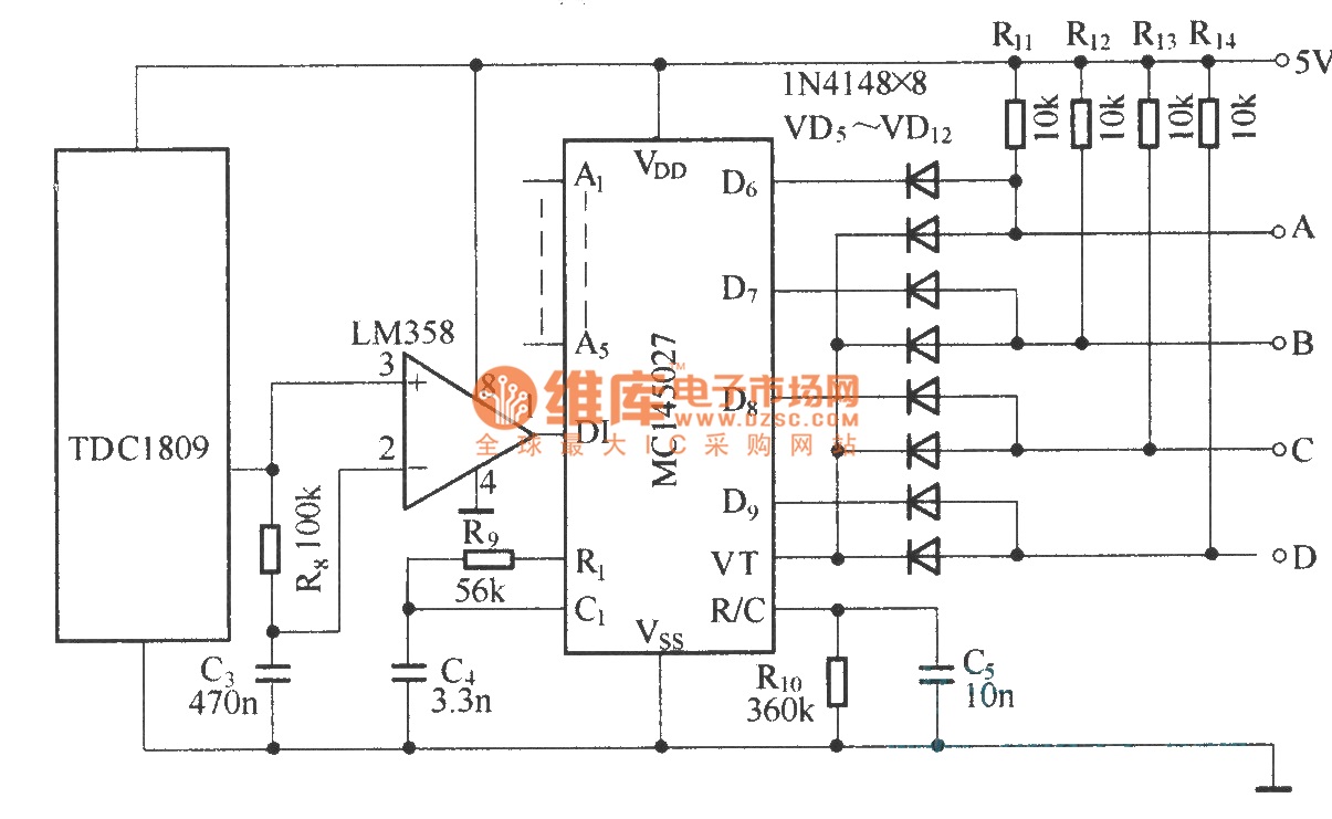
The TDC1808/TDC1809 is a pair of wireless remote control transmitter and receiver components. They utilize an internal antenna to transmit both digital and analog signals. These components are suitable for various wireless remote control devices. Key features include compact...
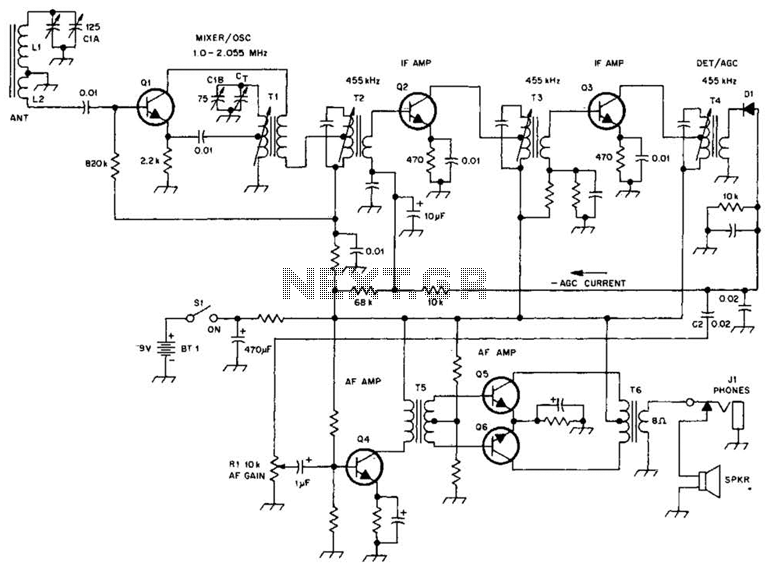
A schematic of a typical transistor AM radio is presented. This circuit utilizes npn transistors. It is a generic circuit; hence, specific values for some components are not provided. This circuit serves as a reference point for experimenters. The schematic...
This is a power-on time delay relay circuit that utilizes the emitter/base breakdown voltage of a standard bipolar transistor. The reverse-connected emitter/base junction of a 2N3904 transistor functions as an 8-volt zener diode, establishing a higher turn-on voltage for...
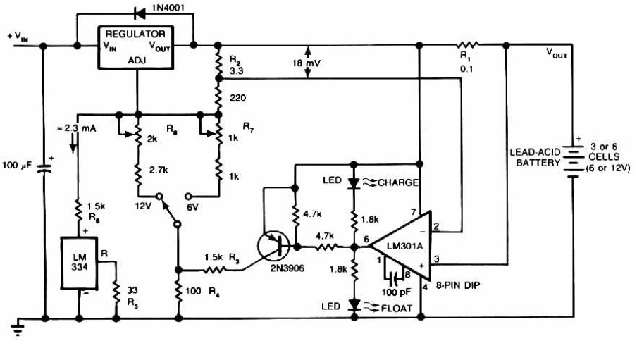
Lead-Acid Battery Charger circuit diagram. The LM301A compares the voltage drop across R1 with an 18 mV reference set by R2. The comparator's output controls the voltage regulator, forcing it to produce the lower float voltage when the battery-charging...
Fuzz is one of the classic guitar effects, and this simple circuit generates it quite well. The circuit is so compact that it can be built into guitars or amps that do not have built-in fuzz to add that...