
Circuit diagram of grundig 5441 tv
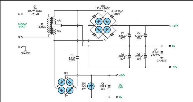
The circuit for the Grundig 5441 television encompasses several key components and functions essential for its operation. The power supply section typically converts mains voltage to the required low voltages needed by various internal circuits. This section may include a transformer, rectifier diodes, and smoothing capacitors to ensure stable DC output.
The main processing unit of the TV is likely based on a microcontroller or a dedicated IC that manages signal processing, user interface, and control functions. Signal input is received through various ports, such as HDMI, composite, or RF, which are routed to a tuner and demodulation circuit for channel selection and processing.
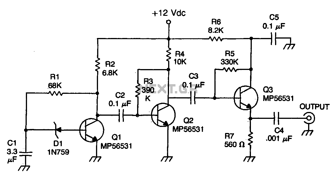
The video and audio signals are then amplified and sent to the output stage, which may consist of a video amplifier and audio amplifier driving the respective display and speakers. Additional components such as feedback loops and filters are included to enhance picture quality and audio fidelity.
The circuit may also incorporate safety features, such as fuses or thermal protection, to prevent damage from overcurrent or overheating. A schematic diagram would typically illustrate the interconnections between these components, showing their arrangement and the flow of signals throughout the circuit.
Overall, the Grundig 5441 TV circuit is designed to provide reliable performance while ensuring user-friendly operation and compliance with safety standards.Circuit for Grundig 5441 tv. If you have any problem regarding this issue come back with more information about the problem, we will glad to assist you By entering the Fixya site you declare that you have read and agreed to its Terms. You may NOT copy or distribute the content that appears on this site without written permission from Fixya
Ltd. © 2005-2014, Fixya, Ltd. or it`s affiliates. 🔗 External reference
Related Circuits
This circuit utilizes a MOSFET amplifier as the primary component for boosting audio signals. It is designed to drive a speaker with an impedance of 8 Ohms and a power output exceeding 200W. Additionally, a suitable power supply circuit...
Voltage regulator ICs from the 78xx series deliver a stable output voltage in contrast to a highly variable input supply, provided that the common terminal is grounded. Any voltage applied above zero volts (ground) to the common terminal is...
The Zener diode functions as an avalanche rectifier in reverse bias mode, connected to the input circuit of a wideband RF amplifier. The noise is amplified and subsequently applied to the cascade wideband amplifier, utilizing transistors Q2 and Q3. The...
Originally, the tank cost around Php 400 but was later sold for approximately a hundred pesos less. Recognizing a great deal, the decision was made to purchase the toy. Opening the toy proved to be somewhat challenging. The track...
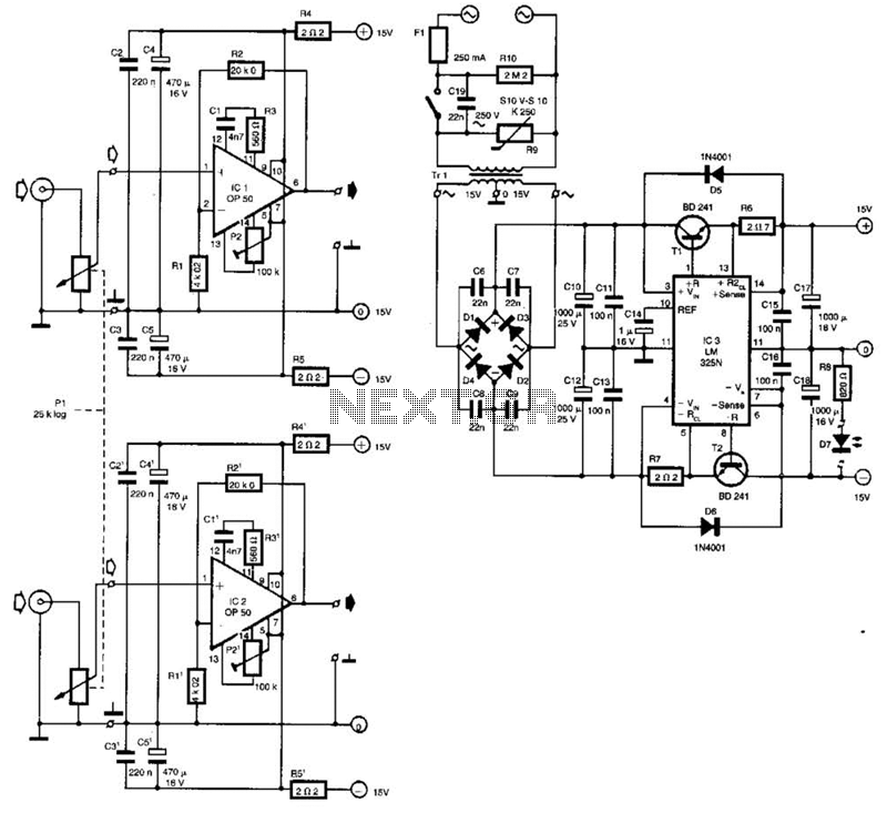
Built around Precision Monolithics Inc. OP-50 operational amplifiers, this amplifier is capable of driving 100- to 14-ohm headphones. It maintains a flat frequency response within 0.4 dB from 10 Hz to 20 kHz and exhibits a total harmonic distortion...
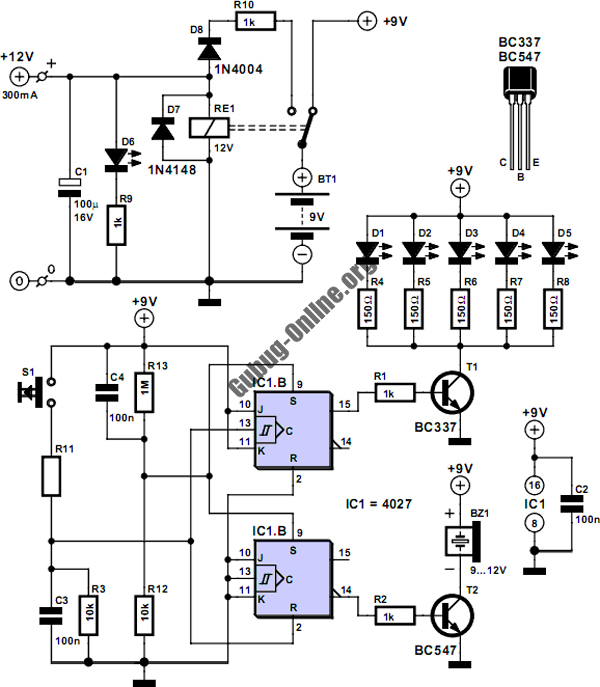
This circuit is designed to control the mains pulse. The pulser's purpose is to switch the mains voltage on and off at intervals ranging from just under one second to a maximum of ten minutes. This functionality is beneficial...
Warning: include(partials/cookie-banner.php): Failed to open stream: Permission denied in /var/www/html/nextgr/view-circuit.php on line 713
Warning: include(): Failed opening 'partials/cookie-banner.php' for inclusion (include_path='.:/usr/share/php') in /var/www/html/nextgr/view-circuit.php on line 713