
Simple MCU-less Differential Motor Drive Circuit
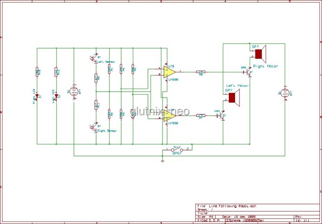
The tank's electronic circuit is a simple yet effective design that utilizes a dual comparator to control motor functions based on surface detection. The use of the LM358-compatible comparator allows for reliable performance and ease of integration. The circuit operates by employing a feedback mechanism through the phototransistors, which serve as light sensors. When the red LEDs emit light onto the surface, the phototransistors detect the reflected light. If the surface is light-colored, the reflected light keeps the phototransistors in a conductive state, allowing the comparator to maintain the motors' operation. Conversely, when the sensors detect a dark surface, indicating a black line, the phototransistors open, causing the comparator to deactivate the motors to prevent the tank from veering off course.
The gearbox design, featuring small DC motors, enables agile movement and precise control over the tracked wheels, facilitating maneuverability. The differential drive system allows for sharp turns and adjustments in movement, enhancing the tank's operational capabilities. The simplicity of the circuit board layout aids in troubleshooting and modifications, making it accessible for hobbyists and engineers alike. This design exemplifies an effective application of basic electronic principles to achieve a functional robotic toy, demonstrating the integration of sensors, motors, and control logic in a compact form factor.Originally, the tank cost around Php400 but then it was sold at around a hundred less. Without thinking twice I know I had a great offer so I decided to buy the toy. Opening the toy was quite a bit tricky. The track belt needs to be removed first and the middle wheels must be pulled out to reveal the two screws joining the tank`s upper body to the lower chassis. Inside it is a little circuit board centered around an SMT IC. Guess what it is, a microcontroller Eeeeeh! You`re wrong. It is controlled by a dual comparator IC which is pin to pin compatible with LM358 (the body marking says it`s 0358 ). Inside the gearbox are two small DC motor no bigger than a cellphone vibrator motor that differentially drive the tracked wheels and, of course, a couple of gears.
Optical sensors are located at the bottom. The main part are the phototransistors (dark part) that detect the reflection (indication that the surface is not black) of the light emitted by the red LEDs (transparent part). The outputs of the comparator provide the drive signal to turn on/off the motors of the tank. It was easy to trace the circuit`s layout since few component resides on the circuit board. Looking at the circuit, we can clearly see a window comparator that turns either of the motor off when the voltage produced by the phototransistors divider network goes beyond the window voltages (most of the time phototransistors are shorted but it opens when it senses a black line).
🔗 External reference
Related Circuits
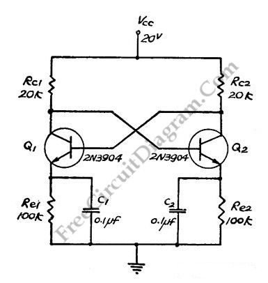
This flip-flop circuit functions as a free-running astable multivibrator, where the bases and collectors of both emitter-biased transistors are directly coupled. The switching action is facilitated by a capacitor in each emitter circuit, resulting in the generation of triangle...
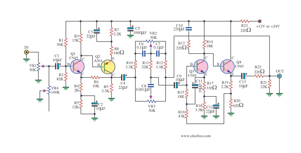
If you have old electronic equipment that has been around for many years, it is beneficial to build a good electronic project. Guidance is requested regarding a pre-tone control circuit for this purpose. A pre-tone control circuit is an essential...
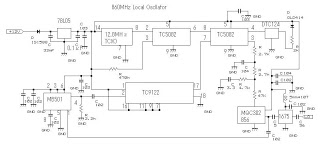
This 860 MHz Phase Locked Loop (PLL) oscillator circuit is designed for a 1200 MHz transverter's local oscillator with 435 MHz rigs. The oscillator utilizes Toshiba PLL synthesizer integrated circuits (ICs). The TC9122P serves as a preset counter for...
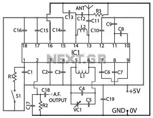
PARTS LIST C1 0.22 µF (224) C2 22nF (223) C3 10nF (103) C4 27pF C5 22pF C6 3.3nF (332) C7 180pF (181) C8 330pF (331) C9 3.3nF (332) C10 150pF (151) C11 82pF C12 68pF C13 220pF (221) C14...
This circuit is straightforward. The initial 555 timer prevents the second timer from being activated while the first is operational. Drive the circuit with a simple 12-volt power supply. The circuit utilizes two 555 timer integrated circuits (ICs) configured in...
The following circuit illustrates a 2500W Phase Control Circuit Schematic. Features include a ground-tied trigger output that is disabled, and a low voltage input. The 2500W Phase Control Circuit is designed to regulate the power delivered to a load by...