
Mains Pulse Circuit
This circuit is an example of a programmable timer relay system that effectively manages the on-off control of mains voltage for various applications. The use of a transformer (Tr1) ensures that the circuit operates safely by stepping down the mains voltage to a manageable level. The bridge rectifier converts the AC voltage from the transformer into a stable DC voltage, which is then regulated to 12V by IC1, providing a reliable power source for the timer IC (IC2) and the relay.
The timer’s configuration allows for flexibility in timing, with the ability to select from four distinct time intervals. This is achieved through the use of jumpers that connect different capacitors, influencing the charge and discharge cycles of the timing capacitor. The option to short-circuit certain positions enhances the functionality by extending the timing range, making it suitable for both short and long operational periods.
The dual preset potentiometers provide further customization, allowing users to fine-tune the on and off durations to meet specific operational requirements. The inclusion of a 1k resistor ensures that the discharge time remains within a safe and functional range, preventing rapid cycling that could lead to relay failure.
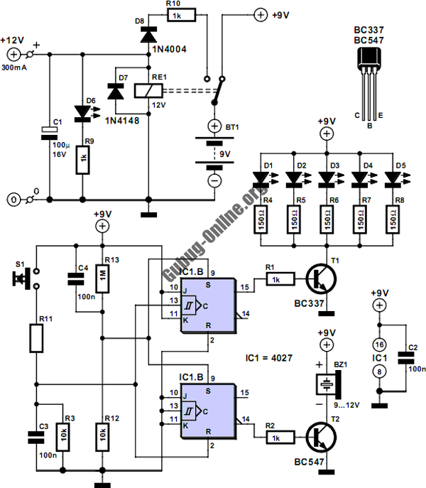
The relay's double-pole contacts are critical for switching the mains voltage, enabling control over larger loads while maintaining safety. The indicator LEDs offer a visual cue of the circuit's operational status, enhancing user interaction and monitoring. The protective fuses are essential for safeguarding the circuit components against potential overloads, ensuring longevity and reliability in operation. Overall, this circuit exemplifies an efficient design for controlling mains voltage in various applications, combining safety features with programmable timing capabilities.This is a circuit that used to main pulse. The pulser is intended to switch the mains voltage on and off at intervals between just under a second and up to 10 minutes. This is useful, for instance, when a mains-operated equipment is to be tested for long periods, or for periodic switching of machinery.
Transformer Tr1, the bridge rectifier, and r egulator IC1 provide a stable 12V supply rail for IC2 and the relay. The timer is arranged so that the period-determining capacitor can be charged and discharged independently. Four time ranges can be selected by selecting capacitors with the aid of jumpers. Short-circuiting positions 1 and 2 gives the longest time, and short-circuiting none the shortest. Here`s the figure of the schematic circuit diagram; In the latter case, the 10 µF capacitor at pins 2 and 6 of the timer IC determines the time with the relevant resistors.
The value of this capacitor may be chosen slightly lower. The two preset potentiometers enable the on and off periods to be set. The 1k resistor in series with one of the presets determines the minimum discharge time. The timer IC switches a relay whose double-pole contacts switch the mains voltage. The LEDs indicate whether the mains voltage is switched through (red) or not (green). The 100mA slow fuse protects the mains transformer and low-voltage circuit. The 4 A medium slow fuse protects the relay against overload. 🔗 External reference
Related Circuits
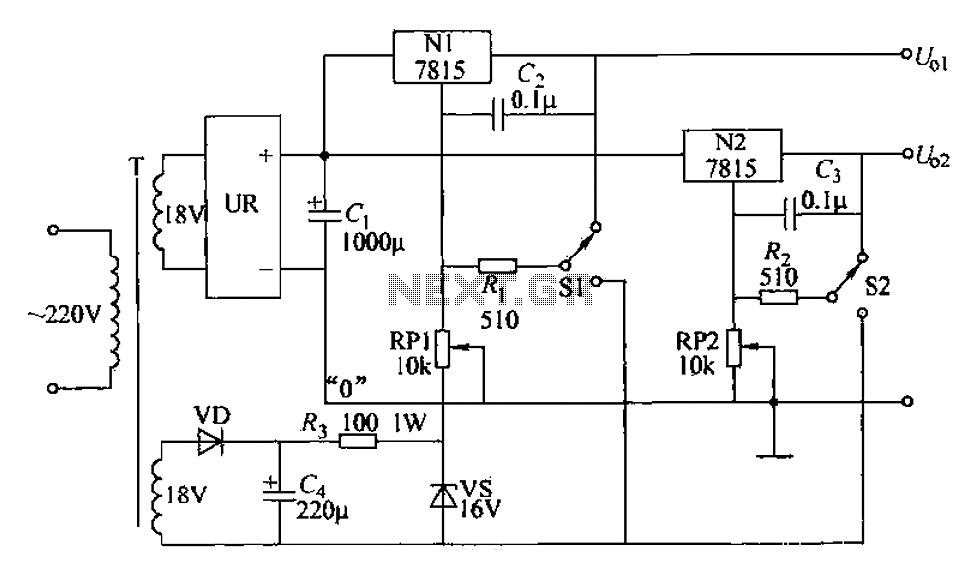
An adjustable dual voltage power supply circuit is presented, suitable for frequent experimental use. The current output does not exceed 1A, and both voltage outputs are adjustable. The circuit utilizes N1, N2, and 78 series three-terminal voltage regulator integrated...
Have you ever attempted to copy a commercially produced video only to end up with a distorted and jumpy image? If so, then you have run afoul of MacroVision. MacroVision is the most popular copy protection scheme used on...
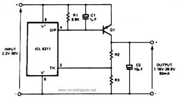
The IC8211 serves as a voltage reference and regulator amplifier, with Q1 likely functioning as the series pass transistor. R1 determines the output current of the IC8211, while C1 and C2 contribute to loop stability and help suppress the...

The circuit diagram illustrates a hum elimination instrument amplifier circuit. The amplifier stages A1 and A2 utilize the integrated operational amplifier INA101, followed by stage A3 which employs the INA105. A feedback circuit is incorporated to reduce the power...
This magic lamp appears to be an ordinary frosted light bulb with a rather unusual characteristic. Whenever a finger touches the base threads and center contact, the lamp magically lights up without wires. It creates a compelling illusion if...
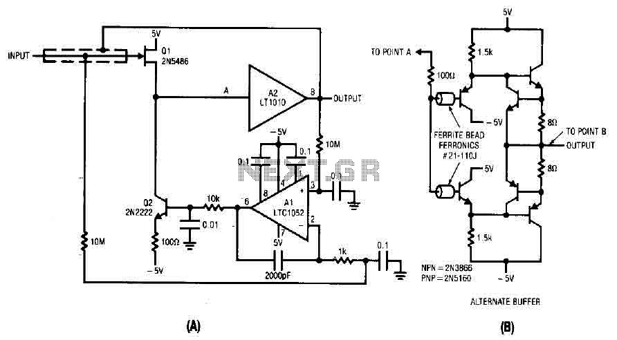
The difference between the amplified signals is utilized to establish the bias for Q1 and Q2 current channels. Q1 regulates the gate-source voltage (VGS) to the necessary level corresponding to the circuit's input and potential output. A 2000 pF...