
Circuit Diagram Of Slave Flash Light Control
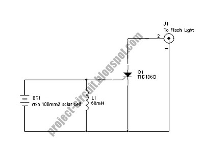
The Slave Flash Light Control Circuit is designed to enhance the functionality of flash lighting systems by enabling a secondary flash light to operate in conjunction with a primary flash. The circuit utilizes a 68 mH inductor, which plays a crucial role in the triggering mechanism. This inductor is responsible for storing energy and releasing it at the appropriate time to activate the secondary flash light.
The circuit typically comprises a power supply, a triggering mechanism, and the flash light components. The power supply provides the necessary voltage and current to the circuit, ensuring that both the primary and secondary flash lights function correctly. The triggering mechanism can be based on various sensors or timing circuits that detect the activation of the primary flash, subsequently sending a signal to the secondary flash light to illuminate.
The design may also incorporate additional components such as resistors, capacitors, and diodes to manage the flow of current, protect against voltage spikes, and filter signals. These elements work together to ensure a reliable and efficient operation of the slave flash light, providing enhanced lighting for photography or other applications where additional illumination is required.
Overall, the Slave Flash Light Control Circuit is an effective solution for achieving synchronized lighting, improving the versatility and performance of lighting setups.The following circuit shows about Slave Flash Light Control Circuit Diagram. Features: 68mH Inductor, give auto trigger for secondary flash light, .. 🔗 External reference
Related Circuits
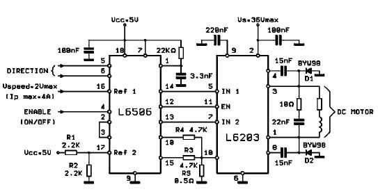
The L620x is a monolithic full bridge switching motor driver implemented using the new Multipower-BCD technology. This technology enables the integration of multiple isolated DMOS power transistors along with mixed CMOS/bipolar control circuits. The L620x series includes various versions:...
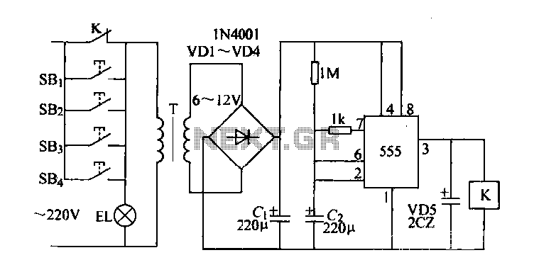
Control buttons SB1 to SB4 can be installed in various positions within a corridor. By pressing any one of these buttons, the EL horse lights will turn on. After releasing the button, the transformer and rectifier supply power to...
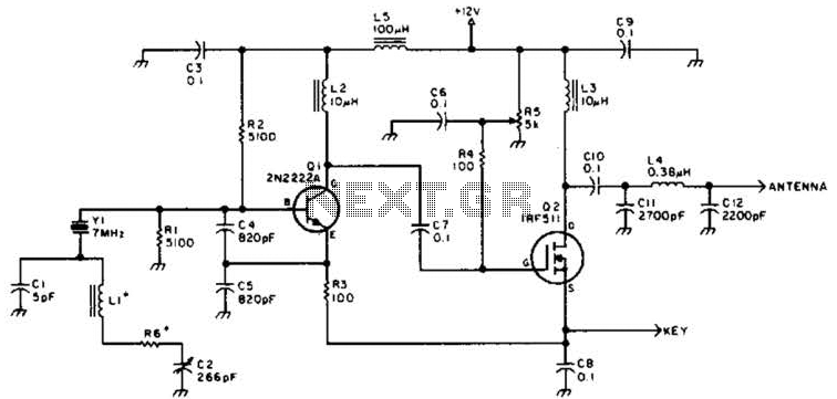
A DSB transmitter is significantly less expensive to construct compared to an SSB transmitter since it does not require filters or phasing networks. This circuit can generate an output of up to 1 watt on the 10-meter band. The...
Remote control utilizing VHF modules. Several designs for remote control switches using the VG40T and VG40R remote control pair are presented here. The miniature transmitter module illustrated in Fig. 1. The VG40T and VG40R are VHF radio frequency (RF) modules...
This is an audio power amplifier that delivers 40 W at 8 ohms in Class A operation. The power transistors are continuously active, enabling a substantial current to flow. The audio power amplifier described operates in Class A mode, which...
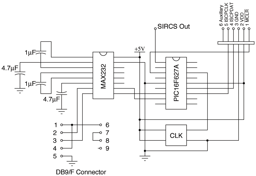
Since building a MythTV, the need for DVD and VCR remote controls was eliminated. However, control over the television remained necessary for functions such as power, volume, mute, and video input selection. Initially, there was uncertainty regarding serial control...
Warning: include(partials/cookie-banner.php): Failed to open stream: Permission denied in /var/www/html/nextgr/view-circuit.php on line 713
Warning: include(): Failed opening 'partials/cookie-banner.php' for inclusion (include_path='.:/usr/share/php') in /var/www/html/nextgr/view-circuit.php on line 713