
Sony TV Control
The circuit utilizes a MAX232 chip to facilitate the conversion of RS-232 signals to logic levels suitable for microcontroller processing. The microcontroller, specifically the Microchip PIC16F627A, is programmed to interpret the incoming commands via its USART interface. This microcontroller is capable of handling serial communication effectively, making it suitable for this application.
The photodiode circuit is designed to detect the IR signals emitted by the RM-Y197 remote control, with sensitivity tuned to 940nm, which corresponds to the wavelength typically used by consumer IR remote controls. The oscilloscope is employed to visualize and verify the timing of the SIRCS protocol, ensuring accurate interpretation of the signals generated by the remote.
The SIRCS protocol involves sending a start bit followed by a series of bits that represent the command and device ID. The microcontroller is programmed to generate these signals in the correct timing sequence, allowing it to control the television effectively. The implementation of a timer within the PIC16F627A is critical for maintaining the timing accuracy required by the SIRCS protocol.
The final schematic diagram illustrates the connections between the MAX232, the microcontroller, and the photodiode, providing a clear representation of the circuit's layout. The inclusion of a Perl script for controlling the device adds flexibility, enabling users to customize the commands sent to the television based on their preferences. The modification of the lircrc file ensures that the MythTV remote can seamlessly interact with the television functions, enhancing the overall user experience.Ever since I built a MythTV, I have been able to eliminate my DVD and VCR remote controls. However, I still needed my television remote control to turn on the TV as well as to control the volume, mute, and video input signal selection. For a while, I didn`t think it was possible to control the TV serially until I was flipping through my Sony TV`s
instruction manual and found a vague paragraph about the Control-S I/O port on the back of the unit. At first glance, this looked like something I would want to use to control my TV from MythTV, but as usual the instruction booklet wasn`t very specific on how I can use Control-S from home-brew devices. Luckily, I found a SIRCS description web page that provided the basic description of the protocol and information that others had found by experimenting with their Sony remote controls.
With so little official documentation and disagreement on the actual timing, I decided to verify their work by building a simple circuit involving a photodiode sensitive to 940nm light and measuring the response of my RM-Y197 television remote control`s IR signal on an oscilloscope. I was able to verify all of the basic codes given on the page referenced above, as well as a few others.
All of the buttons for this particular remote are given below. The last few codes are 15-bits and appear to follow a different protocol than SIRCS. These buttons are for functions which I do not use on my remote, so did not pursue them further. As described on the referred page, SIRCS goes as follows. The start bit is first to be sent, represented as a 2. 4ms high pulse, followed by seven bits representing the functional code (LSB first), the ID of the device (LSB first) which is either a 5-bit or 8-bit code, and a frame space. In the case of this particular remote, a 5-bit ID code is sent (1 (base 10) for TV). The frame is then repeated at least two times. The figure below details the SIRCS waveform. The goal of the hardware is to turn a program code into a modulated signal based on the IR protocol SIRCS.
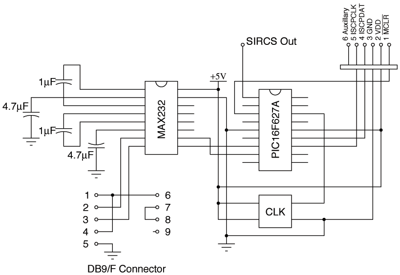
The easist route I saw was to develop a device that would accept one packet from over an RS-232 channel and convert it into the format appropriate for the television. The figure below shows the schematic diagram of the circuit that accomplishes this functionality. A MAX232 chip is used as a level shifter to convert the ±7. 5V signal over the RS-232 line to a 0 to 5V logic level signal. It is fed to a microcontroller where the input code is stored in a register and then each bit is sequentially analyzed and the appropriate timing information is sent over one of the micontroller`s output ports.
The figure below shows the schematic of the final design. For this project, I selected the Microchip PIC16F627A. This 18-pin part included a USART for RS-232 communications to get the 7-bit code from the computer as well as a timer for measuring the 45ms frame. You are welcome to use and adapt the TV controller PIC assembly code. Now that the circuit is built and connected to an open serial port on the computer, it`s time to develop a script that can send a 7-bit control code to the device.
A simple Perl script was written for this task. Feel free to adapt this to your own controller. Next, the lircrc file is modified to map the buttons on my MythTV`s remote to the functions of the Sony remote. Below is a snippet from the modified lircrc file. I have mapped the TV/Video button to the blue button on my Hauppauge PVR-150 remote. Also, be sure to restart lircd after changing your LIRC configuration. 🔗 External reference
Related Circuits

This is a simple toggle switch that can be operated through sound signals such as a whistle or clap. The output of the toggle remains either low or high until... This circuit utilizes a sound sensor to detect specific audio...
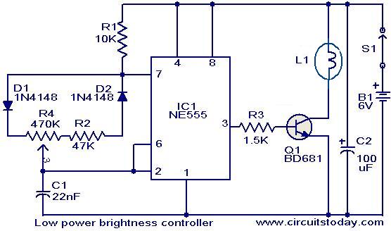
The circuit presented here is designed to control the brightness of low-power incandescent lamps. It utilizes the NE555 integrated circuit, configured as an astable multivibrator with a variable duty cycle. The output from the IC is connected to the...
How can a 1950 Studebaker be enhanced? By installing an iPod Nano in the dashboard. The team at MAYA Design created a touch-controlled sound system for this project, referred to as the "Nano-Baker" or "Stude-iPod," utilizing a pair of...
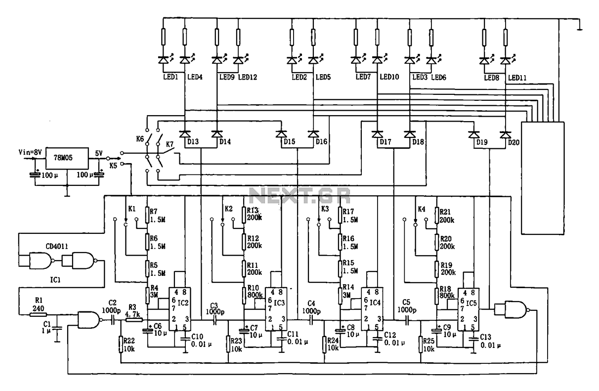
This document describes an automatic traffic intersection light control circuit. It features four monostable delay circuits, which consist of four 555 timer integrated circuits (IC2 to IC5) and several RC components interconnected. An 8V input voltage is regulated through...

A simple oscillator circuit that varies the duty cycle over a wide range without affecting the frequency. It is a variation of the simple 555 astable oscillator. The use of an air-variable capacitor for frequency control is innovative. When...

A DC motor from an old personal stereo cassette player has been utilized in this circuit, which provides control over both the speed and direction of the motor. The circuit employs PWM waveforms to drive a MOSFET H-bridge, as...
Warning: include(partials/cookie-banner.php): Failed to open stream: Permission denied in /var/www/html/nextgr/view-circuit.php on line 713
Warning: include(): Failed opening 'partials/cookie-banner.php' for inclusion (include_path='.:/usr/share/php') in /var/www/html/nextgr/view-circuit.php on line 713