
Circuit Diagram Wiring
The electrical wiring diagram pertains to the 2006 Dodge Grand Caravan model. The troubleshooting manual is organized into five main sections: Wiring Diagram Information, Wiring Diagrams (detailing each component's wiring), Connector Pinouts, Connector/Ground and Splice Locations, and Power Distribution System. The manual provides guidance on utilizing the wiring diagram, circuit information, circuit functions, connectors, ground and splice information, diagnosis and testing of wiring harnesses, electrostatic discharge (ESD) sensitive device standard procedures, voltage potential testing, continuity testing, short to ground testing (on fuses), voltage drop testing, connector removal and installation, terminal removal and installation, and wire splicing. All switches, components, and modules are illustrated in their resting positions with doors closed and the ignition key removed. Components are depicted in two ways: a solid line indicates a complete component, while a dashed line signifies an incomplete component, with a reference number indicating the page where the complete version is found. The list of wiring diagrams included in the manual encompasses the Integrated Power Module, Ground Distribution, Antilock Brakes System, Bus Communication, Power Windows/Door Locks/Mirrors/Seats/Sunroof, Charging and Starting System, Fuel/Ignition System, Navigation/Communications System, Transmission Control System, Vehicle Speed Control, Instrument Cluster, Horn/Cigar Lighter/Power Outlet, Air Conditioning Heater, Occupant Restraint System, Lighting, Audio System, Turn Signals, and Trailer Tow. The handling capability of a power supply system may need verification. Finding a high-power rated variable resistor for load testing can be challenging. A circuit utilizing a 2N3055 power transistor serves as a variable high-power resistor, allowing for current adjustment via a potentiometer. This circuit can replace a load resistor in power supply testing, with a maximum applicable voltage of 60 V. It is crucial to house the circuit in a box with a sufficient heat sink. Although the 2N3055 is rated for a maximum collector current of 15 A, the practical current is limited by the maximum power dissipation of the transistor. When this resistor is not connected to a power supply output, the battery's current consumption is at its maximum due to the absence of voltage reaction from collector current at R2 countering the base current flow for the entire transistor.This Bat Detector Circuit is authored by Chris Eve. Basic tests with a variety of salvaged electret microphones all showed good response to 50kHz and beyond, the smaller the unit the better the response. My tests indicate that a small electret microphone has at least some response to 100kHz and that this response is reasonably flat to at least
50kHz. The microphone I use is approximately 6mm in diameter and can be mounted within the body of a 3. 5mm jack plug. Having the microphone socketed rather than fixed within the detector case is optional, but gives further opportunity to experiment with uni-directional or Pressure Zone modules (see below), or other microphones mounted remotely from the electronics. This bat detector circuit to have better sensitivity, both in distance to a visible bat and in audio frequency, than some other published circuits using a 40kHz transducer with 4000x gain amplification, though the 40kHz transducer I used for the comparison may have a bearing on these results.
The high-pass filter is included purely to help eliminate the circuit being triggered by ambient noise. The filter is a 4-pole Chebychev with a very steep roll-off below 15kHz. There is virtually zero response at 10kHz and below. This type of circuit relies on the wanted signal being loud enough to trigger the CMOS counter, so the less unwanted signal that reaches the circuit the better.
Whilst any of the basic circuits based around a 40kHz transducer will perform adequately for the detection of bats calling within that frequency range, which includes many of the more common species, this circuit will give much better indication of the presence of less-common bats that call at lower frequencies, around 20kHz, as well, hopefully, those at somewhat higher frequencies. When used at dusk, when individual bats are still visible, pointing a unidirectional microphone at a solitary bat indicates a usable range of at least 100ft (30m).
Bats actually call very loudly indeed it`s probably a good job we cannot hear them, else they would keep us awake! This circuit was built in a metal box, because that was what I had to hand, using point-to-point wiring on a ground-plane.
Perforated strip-board should be perfectly adequate and probably a lot easier to fault-find should you make a mistake. I do not have nor intend to produce a pcb layout, so please do not ask for one, though if you should feel the need to produce one and have the inclination to share it I would be only too willing to include it (or a link to it) on this page.
The circuit may be more susceptable to interference from electronic sources if built in a plastic container. Current consumption is around 15mA with no audio output, so a PP3 battery should last for several evenings unless you have got a lot of bats in your area.
For regular or extended use, rechargeable batteries or an external power source would make sense. Note that the LM386 has an absolute maximum voltage of 15v (12v recommended), but the rest of the circuit is OK to 15v. Also be aware, if tempted to use a regulated supply incorporating a 78xx series regulator, that these do generate a lot of noise, so extra filtering could be necessary, especially on the microphone supply.
Component choice for the high-pass filter section is critical for good results, close-tolerance low-noise resistors and capacitors should be used to achieve the expected performance. Similar low-noise components should also be used in the rest of the circuit, (no carbon resistors!), though the tolerances are less critical elsewhere.
Having the microphone and loudspeaker both mounted on/in the detector itself can result in unwanted feedback limiting the volume the speaker can be used at. With the microphone mounted on the detector, simply handling the unit can cause audio output, though this can be reduced to a minimum if the unit is held firmly and moved gently.
Remote mounting of the speaker and/or microphone, the use of a uni-directional microphone module (also helpful to determine where the bat is or for listening to an individual bat), or at least having the speaker facing away from the microphone, all help reduce/eliminate feedback, making it easier to share the experience with others. This electrical wiring diagram apply for Dodge Grand Caravan 2006 model year. the troubleshooting manual is divided into 5 main sections which are Wiring Diagram Information, Wiring Diagrams (outline detail each components wiring diagram), Connector Pinouts, Connector/Ground and Splice Location, Power Distribution System.
Here you will find information about How to Use Wiring Diagram, Circuit Information, Circuit Functions, Connectors, Ground and Splice Information, Diagnosis and Testing of Wiring Harness, Electrostatic Discharge (ESD) Sensitive Device Standard Procedure, Testing of Voltage Potential, Testing for Continuity, Short to Ground Testing (on Fuses), Voltage Drop Testing, Connector Removal and Installation, Terminal Removal and Installation, and Wire Splicing. All switches, components, and modules are shown in the at rest position with the doors closed and the key removed from the ignition.
Components are shown two ways. A solid line around a component indicates that the component is complete. A dashed line around the component indicates that the component is being shown is not complete. Incomplete components have a reference number to indicate the page where the component is shown complete. List of wiring diagrams provided in this manual: Integrated Power Module, Ground Distribution, Antilock Brakes System, Bus Communication, Power Windows/Door Locks/Mirrors/Seats/Sunroof, Charring and Starting System, Fuel/Ignition System, Navigation/Communications System, Transmission Control System, Vehicle Speed Control, Instrument Cluster, Horn/Cigar Lighter/Power Outlet, Air Conditioning Heater, Occupant Restraint System, Lighting, Audio System, Turn Signals, Trailer Tow.
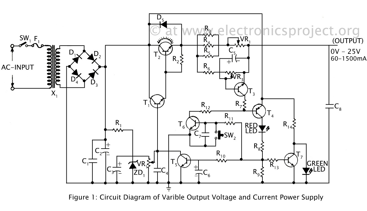
The handling capability of a power supply system is sometimes needed to be checked. It might be difficult to find high power rated variable resistor to provide variable load testing. The following circuit of variable high power resistor uses 2N3055 power transistor to provide the required function : The schematic can replace the load resistor in power supply testing, moreover you can adjust the current by setting the potentiometer. The applicable maximum voltage for this circuit is 60V. Take note to put the circuit in a box with sufficient heat sink. Although 2N3055 is specified for maximum collector current for 15A, but practically the current is limited by maximum power dissipation of the transistor.
When this resistor is not connected to a power supply output then the current consumption of the battery is maximum. This is because there is no voltage reaction coming from collector current at R2 to counter the base current flow for the whole transistor, but it would never eA dual op amp is configured as gone.
🔗 External reference
Related Circuits
This timer was designed primarily to turn off a portable radio after a specific duration. This feature allows users to fall asleep on the beach or in a hammock, with the assurance that the radio will automatically shut off...
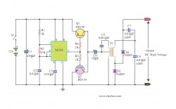
A ripple-free, short-circuit protected variable output voltage and current power supply is presented on this website as a verified project. The circuit diagram includes a description of various power supply circuits. This power supply circuit is designed to provide a...
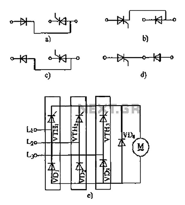
The thyristor linking arm rectifier module is a three-phase half-controlled bridge rectifier circuit. The thyristor-rectifier module linking arm consists of a thyristor and a rectifier diode connected in series or parallel, designed to fulfill specific requirements in power circuits....
An increasing number of appliances draw a very small current from the power supply. If designing a mains-powered device, one can generally choose between a linear and a switch-mode power supply. However, when the appliance's total power consumption is...
This document describes an electronic winding machine with manual, electric, and semi-automatic features. The specific example highlighted includes an electronic counting function that assists users in managing motor windings. The circuit design consists of various components as illustrated in...
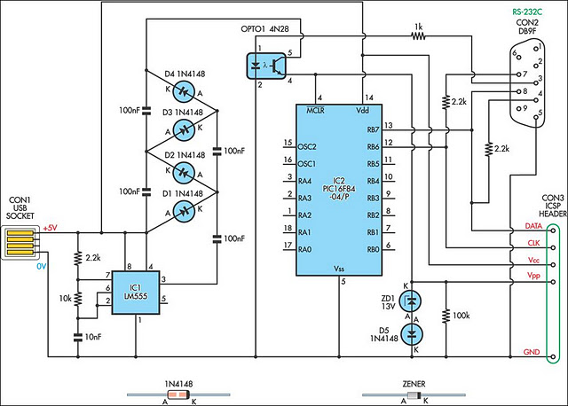
A small biped walker constructed from 2mm plywood, powered by two RC servos. It utilizes the widely available and programmable flash microcontroller PIC16F84. This simple circuit is designed to program the PIC16F84 and similar flash memory components. The project...
Warning: include(partials/cookie-banner.php): Failed to open stream: Permission denied in /var/www/html/nextgr/view-circuit.php on line 713
Warning: include(): Failed opening 'partials/cookie-banner.php' for inclusion (include_path='.:/usr/share/php') in /var/www/html/nextgr/view-circuit.php on line 713