
Thyristor - linking arm rectifier module three-phase half-controlled bridge rectifier circuit
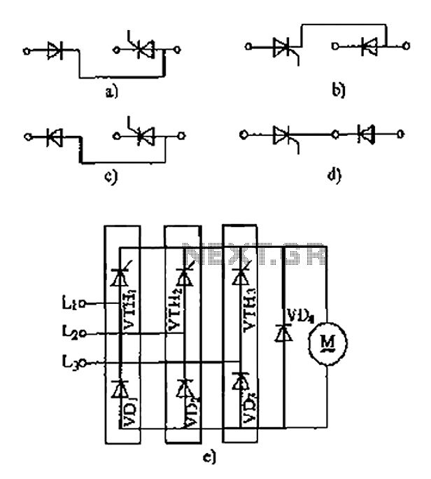
The three-phase half-controlled bridge rectifier circuit utilizes a combination of thyristors and diodes to convert alternating current (AC) to direct current (DC). In this configuration, two thyristors are used for the positive half-cycle of the input AC waveform, while two diodes handle the negative half-cycle. This arrangement allows for controlled rectification, enabling the adjustment of output voltage by varying the firing angle of the thyristors.
In a typical application, the thyristor linking arm module can be employed in industrial power supplies, motor drives, and other systems requiring efficient power conversion. The thyristors are triggered by a control circuit, which determines the timing of the conduction phase, thereby regulating the amount of power delivered to the load. The rectifier diodes provide a path for current during the negative cycle, ensuring continuous operation and reducing ripple in the output DC voltage.
The linking arm design facilitates modularity, allowing for easy integration into various power systems. The series or parallel configuration of the thyristors and diodes can be adapted based on the specific voltage and current requirements of the application. This flexibility makes the thyristor linking arm rectifier module a versatile choice for engineers and designers working on power electronics projects.
In summary, the thyristor linking arm rectifier module is an essential component in modern power electronics, providing an effective means of controlling and converting electrical energy for a wide range of applications. As shown thyristors - linking arm rectifier module three-phase half-controlled bridge rectifier circuit. Thyristor - rectifier module linking arm is made of a thyristor and a r ectifier diode in series or in parallel through the building blocks to meet the needs of some of the power circuit, the common-linked arm module as shown in FIG.
Related Circuits
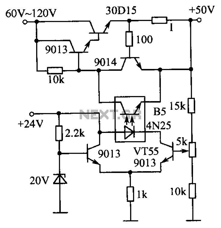
The circuit is illustrated. A standard driving transistor requires a higher breakdown voltage transistor (such as the FIG driving tube 9013). As the output voltage rises, the bias on VT55 increases, leading to an increase in the forward current...
This circuit is a small digital roulette. It consists of an oscillator IC1, a counter IC2, and transistors Q1-7 that drive the common cathode display DSP1. The power supply typically comes from a 9V battery, but it can also...
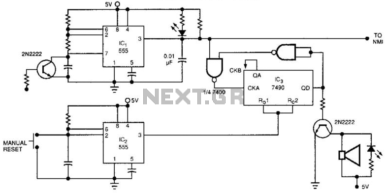
The watchdog timer includes a counter, IC3, alongside the standard retriggerable 555 timer, IC1. The counter will sound an audible alarm if the watchdog timer attempts to reset a specified number of times (8, in the case of the...
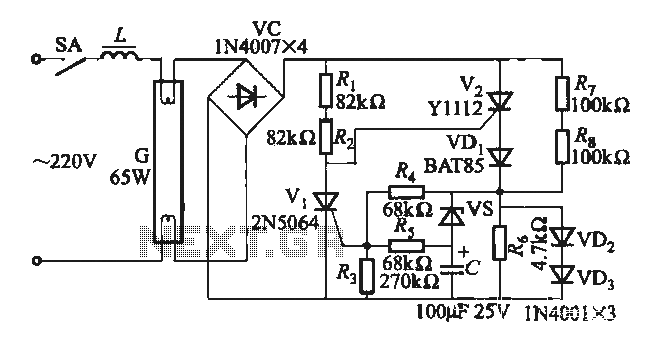
One electronic ballast circuit is depicted in Figure 2-11. This circuit utilizes a specialized fluorescent lamp starter thyristor, SCR Y1112, which is superior to ordinary thyristors due to its ability to maintain a higher current value and dU/dt values....
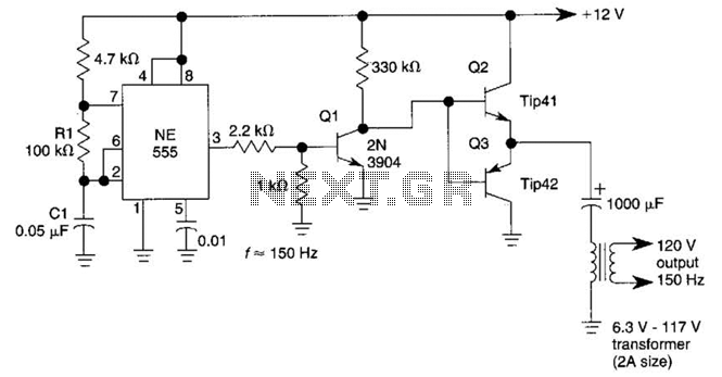
This DC-to-AC inverter utilizes the well-known 555 timer IC. A 555 oscillator circuit drives a buffer amplifier composed of transistors Q1, Q2, and Q3. The circuit operates at a frequency range of 150 to 160 Hz. Transformer T1 can...
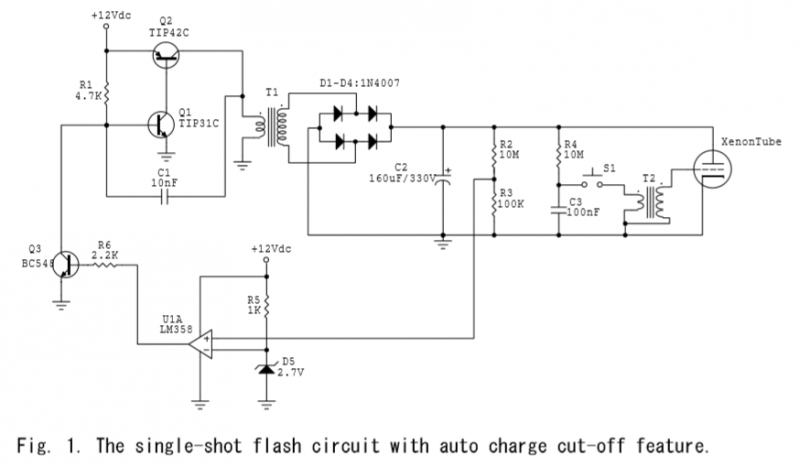
A voltage divider is created using resistors R2 (10MΩ) and R3 (100KΩ), which effectively reduces the voltage across capacitor C2 by a factor of approximately 100. The ground of C2 is connected to the inverter ground for reference. An...
Warning: include(partials/cookie-banner.php): Failed to open stream: Permission denied in /var/www/html/nextgr/view-circuit.php on line 713
Warning: include(): Failed opening 'partials/cookie-banner.php' for inclusion (include_path='.:/usr/share/php') in /var/www/html/nextgr/view-circuit.php on line 713