
Circuit Egg Timer By LM555

The circuit utilizes the popular 555 timer integrated circuit (IC) in astable mode to create a timing function. The configuration allows the user to set a specific time interval during which the circuit operates. The heart of the circuit includes the 555 timer, resistors, capacitors, and a buzzer.
In this design, the timing interval is determined by the values of the resistors (R1, R2) and the capacitor (C1). The output from the 555 timer is connected to a buzzer, which serves as the alarm indicator. When the timer reaches the set interval, the output goes high, activating the buzzer. The circuit can be powered by a standard DC power supply, typically in the range of 5-15V, making it suitable for various applications.
To enhance usability, a potentiometer can be included in the circuit to allow for adjustable timing. The addition of a reset button can also be beneficial, enabling the user to stop the timing process at any point. The overall design is compact and can be easily housed in a small enclosure, making it convenient for portable applications.
This Egg Timer circuit is ideal for cooking, where precise timing is essential, and can be adapted for various other timing applications as needed. The straightforward nature of the circuit makes it an excellent project for beginners in electronics, providing practical experience with the 555 timer IC and basic circuit design principles.This is Easy and Mini Timer Circuit ( Egg Timer) by IC 555. Alarm by Buzzer. This be mini timer circuit that interesting. I calls that Circuit Egg Timer. By. 🔗 External reference
Related Circuits
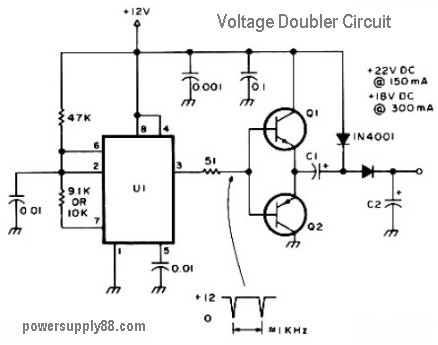
The schematic diagram originates from a 12V DC voltage doubler circuit power supply. This circuit diagram illustrates a DC voltage doubler/DC converter that transforms a 12V DC power supply into 24V DC and 18V DC outputs. It is compatible...
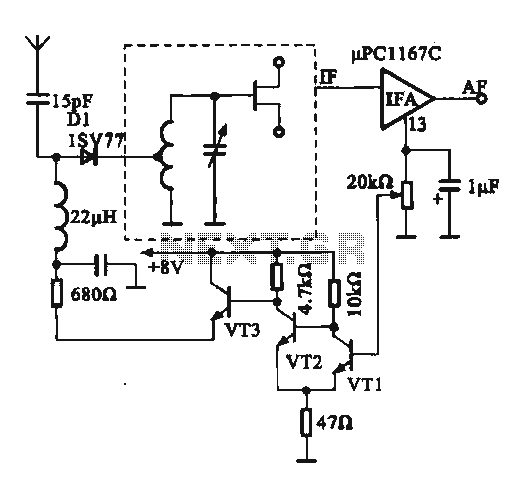
This circuit illustrates an FM modulator with a strong and weak signal switching mechanism. The circuit diagram 3-14 (a) depicts mechanical switches, including a worker selector switch that allows for signal strength selection. Figure 3-14 (b) demonstrates the implementation...
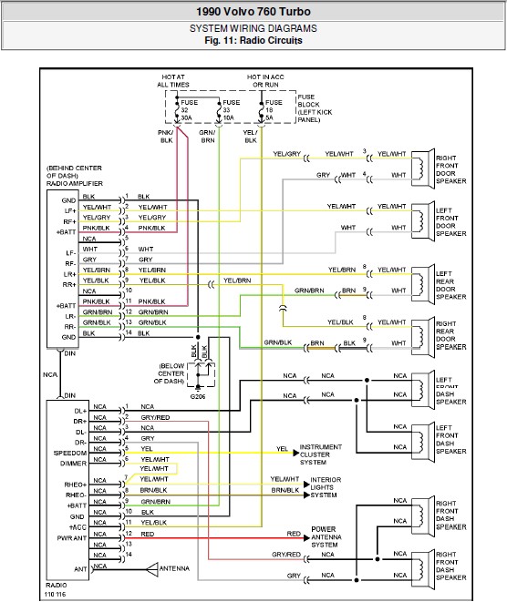
The following document contains the system wiring diagram of the radio circuit for the Volvo 760 Turbo 1990. Please note that this is a system wiring diagram, not a schematic diagram. Download the radio circuit system wiring for the...
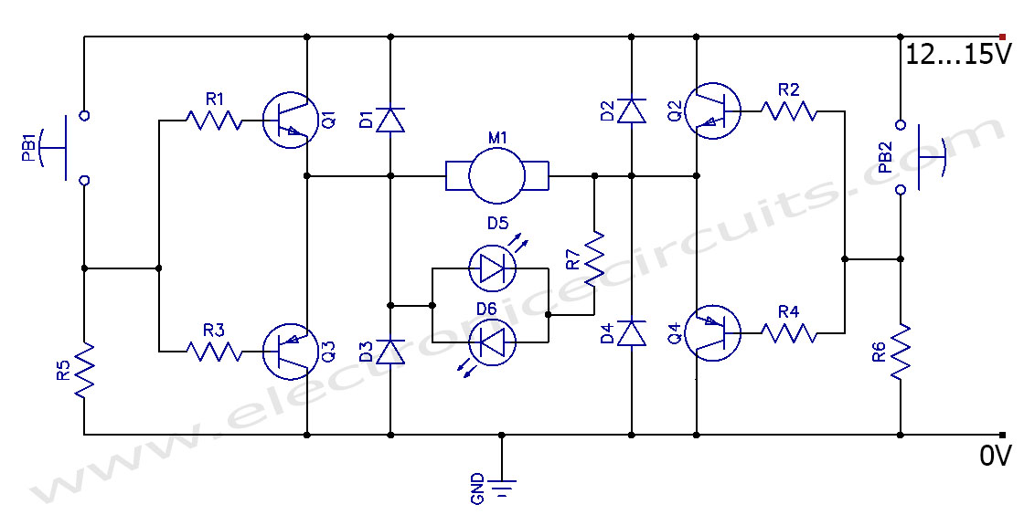
This circuit can control the direction of a DC motor, allowing it to operate in both clockwise and counterclockwise directions (forward and backward). The described circuit employs an H-bridge configuration, which is essential for reversing the polarity of the voltage...

Voltage variations and power cuts adversely affect various equipment such as TVs, VCRs, music systems, and refrigerators. This simple circuit will protect costly equipment from high and low voltages and voltage surges when power resumes. It also produces a...
The circuit below illustrates the use of the LM741 integrated circuit (IC) in a light and dark sensor configuration. This circuit offers several features, including a 1 Watt LED spotlight, making it suitable for a wide range of renewable...