
555 timer mono stable one shot circuit
The circuit utilizes the 555 timer in monostable mode, where it is triggered by a momentary push button. The 555 timer is a versatile integrated circuit widely used for timing applications. In this configuration, pressing the button momentarily connects pin 2 (trigger) to ground, resulting in a low voltage that triggers the timer. The output at pin 3 then transitions from low to high, activating the relay or other connected load.
The timing period is determined by the values of the timing capacitor (22uF) and the resistor (100K) in the circuit. The time duration can be calculated using the formula T = 1.1 * R * C, where T is the time in seconds, R is the resistance in ohms, and C is the capacitance in farads. In this case, with R = 100,000 ohms and C = 22 * 10^-6 farads, the timing period is approximately 2.42 seconds.
The circuit is designed to ensure that the relay operates reliably even with minor fluctuations in supply voltage, as the output at pin 3 remains stable until the timing capacitor reaches the designated threshold. The inclusion of the diode helps protect the timer from back EMF generated by the relay, which can occur when the relay coil is de-energized. Overall, this circuit exemplifies a practical application of the 555 timer in controlling a relay with a momentary switch, providing a simple yet effective solution for timed operations in various electronic projects.The two circuits beneath allegorize application the 555 timer to abutting a broadcast for a agreed bulk of time by acute a cursory N/O advance button. The ambit on the larboard can be acclimated for continued time periods area the advance button can be apprenticed and appear afore the end of the timing period.
For beneath periods, a capacitor can be acclimated to abstract the about-face so that alone the antecedent about-face cease is apparent by the timer ascribe and the about-face can abide bankrupt for an absolute aeon after ability the output. In the abandoned state, the achievement at pin 3 will be at arena and the broadcast deactivated. The activate ascribe (pin 2) is captivated aerial by the 100K resistor and both capacitors are discharged.
Back the button is closed, the 0. 1uF cap will allegation through the button and the 100K resistor which causes the voltage at pin 2 to move low for a few milliseconds. The falling voltage at pin 2 triggers the 555 and starts the timing cycle. The achievement at pin 3 anon moves up to abreast the accumulation voltage (about 10. 4 volts for a 12 volt supply) and charcoal at that akin until the 22 uF timing capacitor accuse to about 2/3 of the accumulation voltage (about 1 additional as shown).
Most 12 volt relays will accomplish at 10. 4 volts, if not, the accumulation voltage could be aloft to 13. 5 or so to compensate. The 555 achievement will accumulation up to 200mA of current, so the broadcast could be replaced with a baby lamp, doorbell, or added amount that requires beneath than 200mA. Back the button is released, the 0. 1uF capacitor discharges through the 100K and 2K resistors. The diode beyond the 100K resistor prevents the voltage at pin 2 from ascent aloft the accumulation voltage back the cap discharges.
The 2K resistor in alternation with the 22uF cap banned the acquittal accepted from pin 7 of the timer. This resistor may not be necessary, but its a acceptable abstraction to absolute accepted back absolution capacitors beyond about-face contacts or transistors.
🔗 External reference
Related Circuits
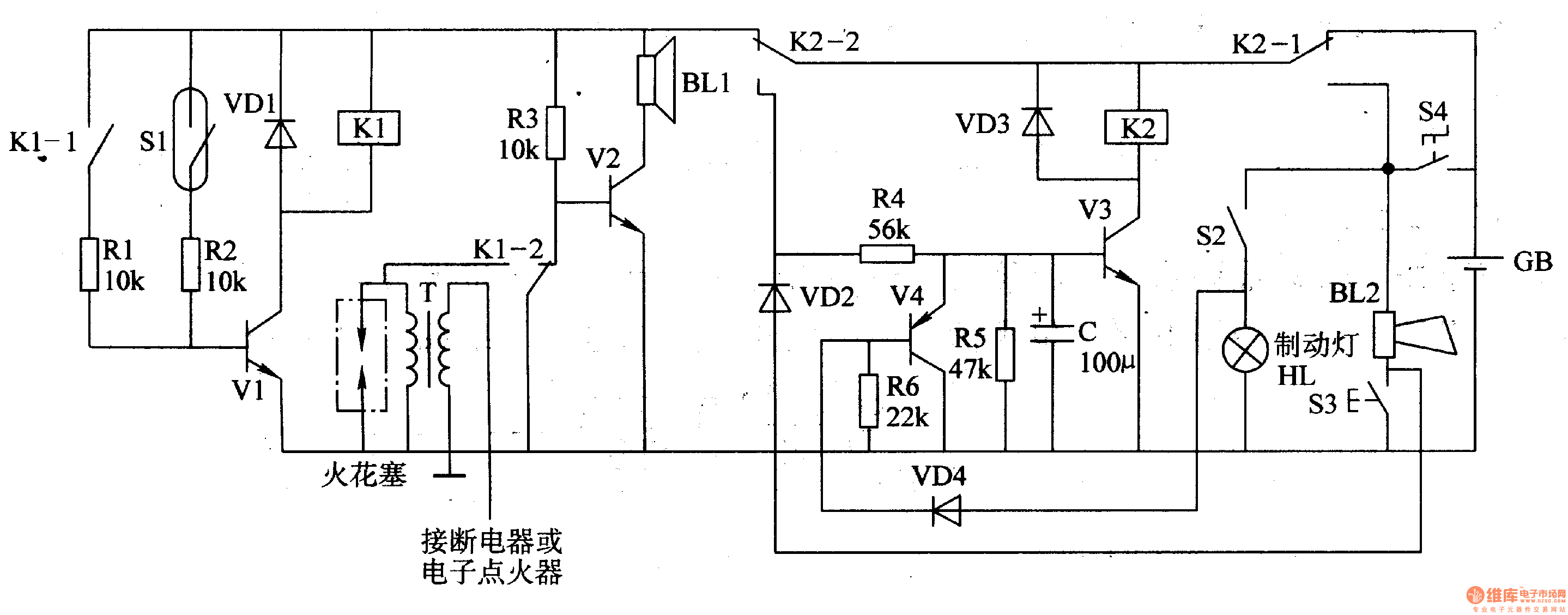
The circuit comprises a trigger circuit, an alarm control circuit, and a reset circuit for the alarm. The trigger circuit includes mercury switches (S1), a resistor, transistors (V1), and a relay (K1). The alarm control circuit is made up...

In the production of LCD projectors, the primary factor threatening the lifespan of the LCD screen is the temperature generated by halogen lamps. The multi-function controller designed by this circuit is highly effective for protecting liquid crystal projectors. The...

This solar battery charger is a simple and cost-effective project suitable for hobbyists. While it has some limitations compared to other similar devices, it offers several advantages. The charger is designed for lead-acid batteries but can also charge any...
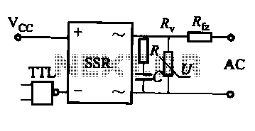
This document discusses the AC solid-state relay (AC-SSR) and presents its basic application circuit as illustrated in Figure (a). Additionally, it includes a TTL drive SSR circuit depicted in Figure (b), a CMOS driver circuit for the SSR shown...
The stroboscope tube requires approximately 250-400V DC for operation. This high voltage is generated by a simple voltage step-up circuit constructed from transistors Q1, Q2, and transformer T1. This circuit outputs about 230V AC, which is then rectified by...
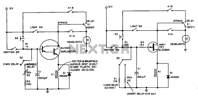
This circuit maintains the headlights of an automobile in an on state temporarily. It also ensures that the lights turn off automatically, even if the user forgets to switch them off manually. The shut-off delay is activated only when...
Warning: include(partials/cookie-banner.php): Failed to open stream: Permission denied in /var/www/html/nextgr/view-circuit.php on line 713
Warning: include(): Failed opening 'partials/cookie-banner.php' for inclusion (include_path='.:/usr/share/php') in /var/www/html/nextgr/view-circuit.php on line 713