
Tachometer Circuit Using LM2907 LM2917 Frequency to Voltage Converter

The LM2907 integrated circuit is specifically designed for frequency-to-voltage conversion applications, making it suitable for tachometer designs. The circuit operates by detecting the zero crossing of an input signal, which is typically derived from a rotating shaft or similar mechanical component. The charge pump within the LM2907 is responsible for generating a voltage pulse each time the input signal crosses zero volts. This pulse is then used to trigger further processing within a digital system, such as a microcontroller or a microprocessor.
Capacitor C1 plays a crucial role in determining the characteristics of the output pulse. The choice of capacitance directly influences the width of the pulse generated, which is essential for ensuring accurate frequency measurement. The internal current at pin 2 of the LM2907, which can vary based on circuit configuration and design, also affects the pulse duration. The relationship between these parameters is critical for achieving the desired performance from the tachometer circuit.
The circuit is designed to operate with a DC power supply, typically within the range of 12 to 15 volts, which provides adequate headroom for stable operation of the LM2907. The input signal can accommodate a wide range of voltages, allowing the circuit to be versatile in various applications. The capability to handle input voltages from ±20 mV to ±28 V makes the circuit suitable for diverse sensor outputs.
The output pulse characteristics, including width and height, are essential for interfacing with digital systems. The pulse width formula (VCC/2) x (C1/I2) allows for precise calculations to ensure that the output pulse meets the timing requirements of the subsequent digital processing unit. The pulse height, determined by the Zener voltage, provides a stable reference level for the digital system, ensuring reliable operation.
In summary, the LM2907-based tachometer circuit is a versatile and efficient solution for frequency measurement applications, providing essential features such as zero-crossing detection, pulse generation, and compatibility with a wide range of input signals and power supplies.This is a design circuit for tachometer circuit based on the LM2907 IC can be used to provide zero crossing datum to a digital system. At each zero crossing of the input signal the charge pump changes the state of capacitor C1 and provides a one-shot pulse into the zener diode at pin 3.
The width of this pulse is controlled by the internal current of pin 2 and the size of capacitor C1 as well as by the supply voltage. This is the figure of the circuit; Since a pulse is generated by each zero crossing of the input signal we call this a ``two-shot`` instead of a ``one-shot`` device and this can be used for doubling the frequency that is presented to the microprocessor control system. This electronic tachometer circuit project can be powered from a 12, 15 volt DC power supply circuit.
Input can be from plus /minus 20 mV to plus/minus 28V. Pulse width is equal with (VCC/2)x(C1/I2) and the Pulse height is equal with VZENER. 🔗 External reference
Related Circuits
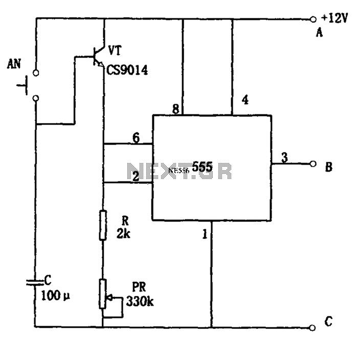
The circuit features a straightforward long timing mechanism. Activating switch AN initiates the timing process, while tone PR allows for timing adjustments. The timing range spans from 3 minutes to 220 minutes. With a capacitance value of 2200 µF,...
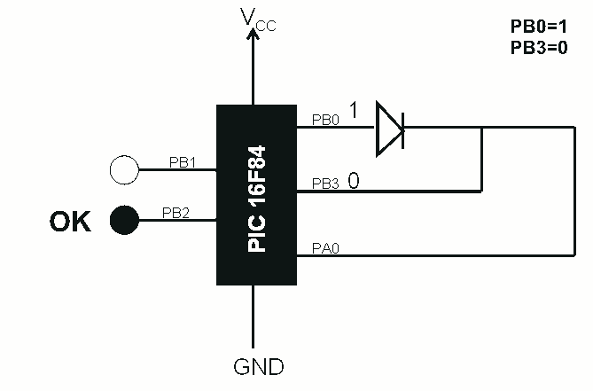
This is a simple use of the PIC 16F84 about a diode tester. Test procedure: We set "1" to PB0 and "0" to PB3. If the diode is ok and opens, then at PA0 we have "1". If PA0...
The 2N3819 is an n-channel JFET specifically designed for RF and mixer applications, offering very low noise, minimal distortion, and excellent high-frequency gain. Creating a PCB can be accomplished in a few straightforward steps. Begin by using PCB design...
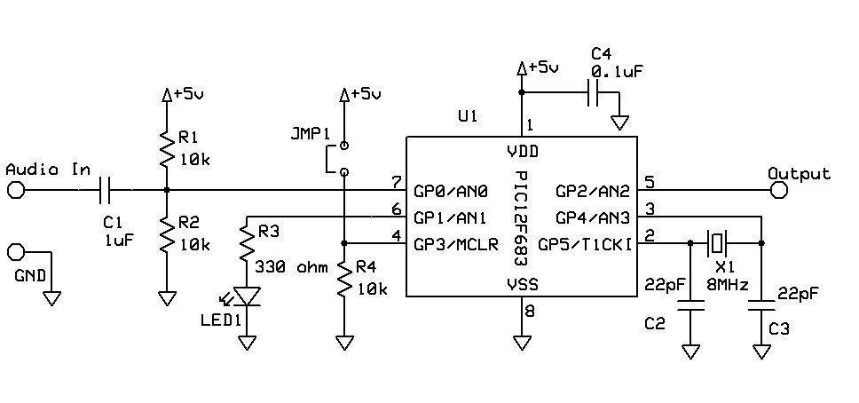
DTMF Touch Tone Decoder Using Microchip PIC Microprocessor. This project contains the details of using a Microchip PIC12F683 8-bit microprocessor to detect Dual-Tone Multi-Frequency (DTMF) signals. The DTMF Touch Tone Decoder circuit utilizes the Microchip PIC12F683 microprocessor, which is an...
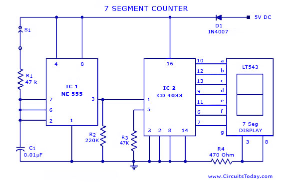
A simple seven-segment counter circuit with an LED display. This counter circuit diagram is designed using the IC CD 4033 as a counter, a 555 Timer IC, and a seven-segment LED display LT 543. The seven-segment counter circuit utilizes the...
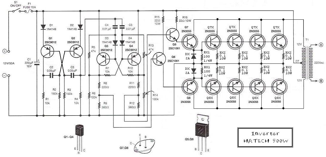
This is the schematic diagram of a 500W power inverter circuit built using 10 pieces of well-known NPN power transistors, 2N3055, to amplify the AC signal produced by a multivibrator. The frequency generator/multivibrator is also constructed using transistors. All...