
Low-pass filter circuit diagram subwoofer

The subwoofer low-pass filter circuit is designed to effectively manage audio signals by allowing low-frequency sounds to pass while attenuating higher frequencies. The TL062's dual configuration allows for efficient signal processing, where the first operational amplifier (IC1a) serves to mix and amplify the audio signals from both left and right channels. This configuration is particularly beneficial for audio applications, as it maintains signal integrity and minimizes distortion.
The adjustment of gain through potentiometer R3 enables fine-tuning of the output level, accommodating various audio sources and preferences. The filter network, composed of resistors and capacitors, is crucial for defining the cutoff frequency of the low-pass filter, which determines the range of frequencies that will be passed to the subwoofer. The values of R5, R6, R7, R8, C4, and C5 should be selected based on the desired cutoff frequency and the specific characteristics of the audio system.
The second operational amplifier (IC1b) acts as a buffer, providing a high input impedance and low output impedance, which is essential for driving the subsequent stages of the audio system without loading down the previous stage. This configuration ensures that the filtered output maintains fidelity and is suitable for driving a subwoofer.
When assembling the circuit, it is critical to use a high-quality printed circuit board to minimize noise and interference, which can adversely affect audio performance. The dual power supply requirement of +12/-12 V DC is standard for operational amplifier circuits, ensuring that the amplifiers function within their optimal voltage range. Proper installation of the TL062 in its holders is essential for reliable operation and to avoid connection issues that could lead to circuit failure. Overall, this subwoofer low-pass filter circuit is a robust solution for enhancing audio playback in subwoofer applications.Many subwoofer low-pass filter circuit , this is just another. Circuit given here are based on discharge from ST Microelectronics shipped TL062. TL062 is a dual high input impedance J - FET operational amplifier with very low power consumption and high slew rate. Operational amplifier with excellent audio features, this track is very suitable. Inside two TLC062 operational amplifier, the first one is wired as a mixer and preamplifier stage. Left and right channel is connected to the inverting input IC1a mixing. The first stage of the gain can be adjusted using the output of the first stage is pot R3.The network through the filter assembly R5, R6, R7, R8, C4 and C5 is connected to the input of the second stage. The second operational amplifier (IC1B) as a buffer, in 7 feet of TLC062 and filter the output. Schematic Precautions Good quality printed circuit board assembly. The circuit can be +12 / -12 V DC dual power supply. In IC1 holders must be installed.
Related Circuits
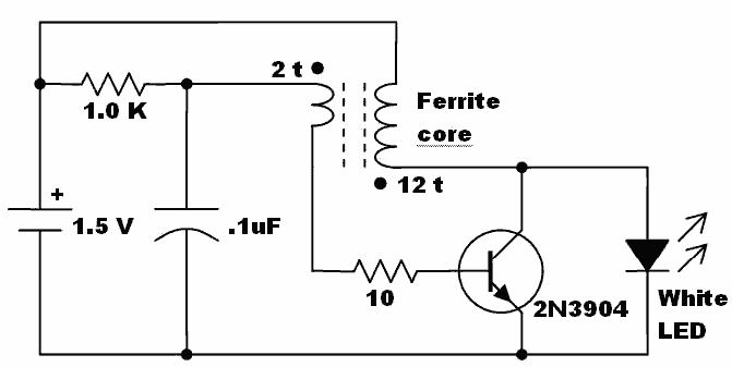
Here is an idea for a voltage booster that enables the lighting of a white LED using a single AA cell. This presents an opportunity to utilize one of the ferrite cores and white LED holiday lights mentioned in...
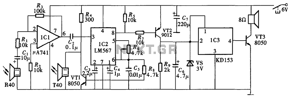
The Blind Pathfinder circuit primarily consists of the A741 operational amplifier, LM567 phase-locked loop, KD153 transistor, 8050 transistor, 9012 transistor, and various other components. The Blind Pathfinder circuit is designed to assist in navigation and obstacle detection, typically utilized in...
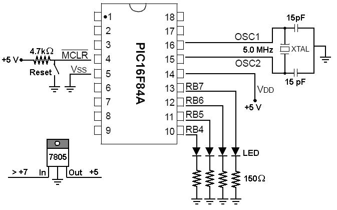
To start working with microcontrollers, several essential items are required. The PICSTART Plus kit, part number DV003001, was purchased from Microchip. This kit contains a sample PIC16F84 microcontroller chip, which in this case is a PIC16F84A chip. This chip...
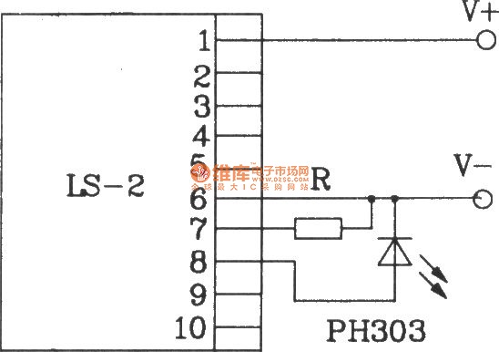
The LS-2 remote control switch infrared sensor module is similar to the LS-18 but functions as a reflector. The LS-2 pin diagram and internal block diagram provide insights into its electrical parameters. The operating voltage for the LS-2 remote...
Modern exhibitions utilize extensive sound, light, and electrical technologies for advertising, promotion, and propaganda. This involves various electrical diagrams and control models. Commonly used is an automatic program circuit with pre-recorded commentary, which requires synchronization of two mating times....

The servo motor is a type of traditional motor that serves as the execution component in automated devices. Its most significant characteristic is its controllability; when a control signal is applied, the servo motor rotates, with its speed being...