
Variable Dc Power Supply

The Variable DC Power Supply circuit typically employs a linear voltage regulator, such as the LM317, which allows for adjustable output voltage. The design incorporates a potentiometer to set the desired output voltage, which can be varied from 1.25V to 24V. The circuit also includes a current limiting feature, often implemented using a resistor in series with the load and a transistor to control the current flow. This configuration ensures that the output current does not exceed 2A, protecting both the power supply and the connected load from damage due to overcurrent conditions.
The power supply is built around a transformer that steps down the AC mains voltage to a lower AC voltage suitable for the regulator. After rectification using a bridge rectifier, the pulsating DC is smoothed out using filter capacitors to provide a stable DC voltage to the regulator. The output of the regulator is then further filtered to minimize ripple, ensuring a clean and stable DC output.
In terms of safety features, the circuit can include fuses and thermal protection to prevent overheating. Additionally, heat sinks may be employed on the voltage regulator to dissipate heat generated during operation, especially when delivering higher currents.
For customization, users can adjust component values based on their specific needs, such as modifying the output voltage range or current limit. The circuit can also be enclosed in a robust casing with appropriate connectors for ease of use in various applications, making it an essential tool for electronics enthusiasts and professionals alike.A Variable DC Power Supply is one of the most useful tools on the electronics hobbyist`s workbench. This circuit is not an absolute novelty, but it`s simple, reliable, "rugged" and short-proof, featuring variable voltage up to 24V and variable current limiting up to 2A. It`s well suited to supply the circuits shown in this website. You can adapt i t to your own requirements as explained in the notes below. 🔗 External reference
Related Circuits
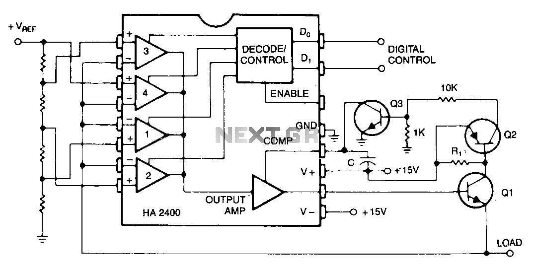
Many systems require one or more relatively low-current voltage sources that can be programmed to a few predetermined levels. The circuit presented generates positive output levels but can be modified for negative or bipolar outputs. Q1 serves as the...
This document presents a very low-power monolithic 1.9GHz silicon Low Noise Amplifier (LNA) that operates with a total current consumption of 1.75mA, which includes the bias circuit. The described Low Noise Amplifier (LNA) operates at a frequency of 1.9GHz, making...
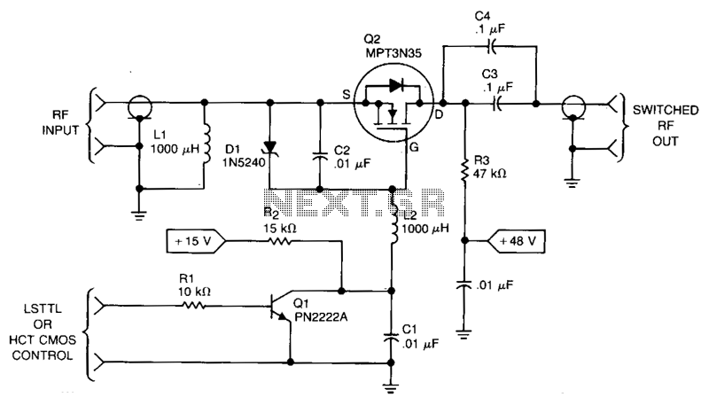
This RF power switch operates at 1.7 MHz with a 50-V source and load. Its on-loss is 0.2 dB, and its off-isolation is 30 dB. It provides 40-W PEP, 45 V_RMS, and 0.9 A_PEAK. The control input can come...
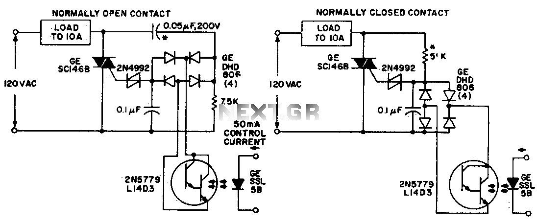
Both circuits utilize the GE SC146B, a 200 V, 10 A Triac for load current contacts. These triacs are activated by standard SBS (2N4992) trigger circuits, which are managed by a photo-Darlington configuration, functioning through the DA806 bridge as...
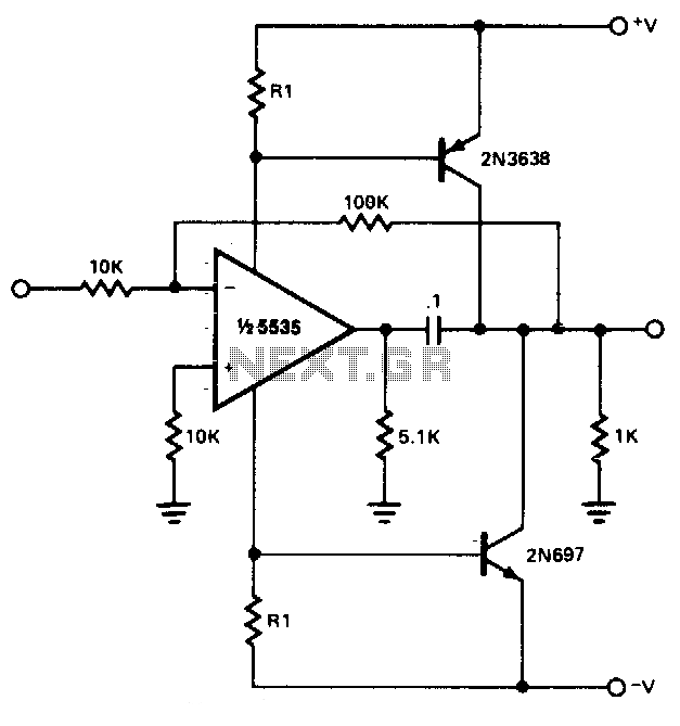
The power booster is designed to drive moderate loads. The circuit utilizes a NE5535 device. Other amplifiers may be substituted, provided that the resistor values (R1) are adjusted according to the Icc current requirements of the chosen amplifier. Additionally,...
Some amplifier is based around a RF transistor. In my case I will use a common NPN RF transistor called 2SC1970. You can also use other transistors like 2N4427 and some others. Check datasheets to see how much power...