
Circuit Reads Encoder Direction of Movement
The direction discriminator circuit is constructed using a dual monostable multivibrator, which can be selected based on the application’s speed needs. Feedback from one of the outputs to an input is utilized to prevent re-triggering, which, while not strictly necessary, aids in maintaining a constant pulse duration. A critical function of this circuit is to trigger forward pulses from one edge of the input signal and reverse pulses from the opposite edge (as shown in Figure 2).
The oscilloscope printout illustrates the circuit's behavior when the encoder shaft is slightly moved between clockwise and counterclockwise positions. Channel 1 corresponds to Channel A (U1 pin 4), Channel 2 to Channel B (pin 13), Channel 3 to Out Forward (pin 6), and Channel 4 to Out Reverse (pin 10). Consequently, the same mechanical position or edge of the encoding wheel produces a positive edge in the forward direction and a negative edge in the reverse direction. If the design utilizes the same electrical edge for triggering, this results in a hysteresis effect when changing the direction, typically one encoder slot width, which is usually half of the encoder's rated resolution (as illustrated in Figure 3). This can lead to accuracy issues, especially if the encoder experiences mechanical jitter or vibration around the clocking edge.
The circuit employing a D flip-flop may introduce inaccuracies at the direction reversal point, particularly when the encoder is undergoing jittering. Careful consideration must be given to the output pulse duration of the monostables. For medium-scale integrated (MSI) logic counters, such as the 193, a pulse duration of 200 ns is generally sufficient. However, in cases where a microprocessor is counting the forward and reverse signals via its interrupt inputs, the pulse length must exceed the maximum microcontroller (MCU) interrupt response time. Often, this necessitates pulse lengths of several tens of microseconds, as seen in the circuit of Figure 1, where the pulse width is approximately 50 µs. Once the pulse length is established, the maximum speed or encoder frequency can be calculated, which in this example is approximately 5 kHz (as shown in Figure 4).
The circuit will not cease to function if the frequency exceeds the specified limits; however, beyond the maximum frequency, the output pulse duration will be truncated from the triggering edge (Channel A) to the falling edge (Channel B). This observation allows for a potential simplification of the circuit shown in Figure 1. By removing resistors R1 and R2, with only minor adjustments to the circuit's response, the output pulse will consistently represent the time from the triggering edge of Channel A to the falling edge of Channel B (as depicted in Figure 5).Incremental-rotation or linear encoders are very common, but normally they do not provide a direction signal. This design shows an easy way to detect forward or reverse direction. Incremental encoders normally provide two output signals, usually named Channel A and Channel B. These signals deliver both clock information, depending on resolution, a nd rotating speed. They differ only in phase margin (for example, 90 ° for clockwise and +90 ° for counter clockwise). The circuit in Figure 1 uses these signals as inputs to a 4538 single-chip, dual monostable multivibrator. Depending on the speed required for the application, the IC could be a metal-gate device, a 74HC, or a 74HCT type.
1. The direction discriminator circuit is based on a dual monostable multivibrator, which can be a metal-gate, 74HC, or 74HCT type depending on the speed required by the application. The feedback from one of the outputs to an input is used to avoid re-triggering. This isn`t strictly necessary but helps to keep the pulse duration constant. On the other hand, an important function is to trigger forward pulses from one edge of the input signal and reverse pulses from the other edge of that signal ( Fig.
2 ). 2. This scope printout shows the behavior of the circuit when the encoder shaft is moved a little between clockwise and counter-clockwise. Channel 1 is In Channel A (U1 pin 4). Channel 2 is In Channel B (pin 13). Channel 3 is Out Forward (pin 6). Channel 4 is Out Reverse (pin 10). This is why the same mechanical position, or slot edge of the encoding wheel, delivers, for instance, a positive edge in the forward direction and a negative edge in reverse.
So if a design uses the same electrical edge for triggering, the result will be a hysteresis in changing the direction of one encoder slot width, which is normally one half of the rated encoder resolution ( Fig. 3 ). This can create accuracy problems that get even worse if the encoder is mechanically jittering (vibrating) around the clocking edge.
3. This circuit using a D flip-flop can cause inaccuracies at the point of reversing the direction, especially when the encoder is jittering (vibrating) around the clocking edge. The designer should use care in determining the output pulse duration of the monostables. If medium scale integrated (MSI) logic counters like the `193 are used, 200 ns will be enough, but sometimes a microprocessor using its interrupt inputs counts the forward and reverse signals.
This requires a pulse length of at least the maximum MCU interrupt response time. In many cases, this may be pulse lengths of some tens of microseconds as in the circuit of Figure1, where the pulse width, tPLS ‰ 50 µs. Once the pulse length is known, the maximum speed is determined by: So, the maximum speed or encoder frequency in this example is approximately 5 kHz ( Fig.
4 ). The circuit won`t totally stop working if overdriven in frequency, but beyond the maximum frequency the duration of the output pulse will be cut to a length from the triggering edge (Channel A) to the falling edge (Channel B). This leads to a possible simplification of the circuit in Figure 1. If you eliminate resistors R1 and R2, the output pulse would always be the time from the triggering edge of Channel A to the falling edge of Channel B ( Fig.
5 ). 5. Resistors R1 and R2 in the direction discriminator circuit can be removed with only minor changes to the circuit`s response. Again, the scope`s traces are the same as those in Figure 2. 🔗 External reference
Related Circuits
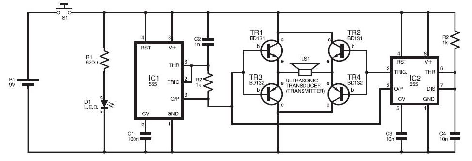
This ultrasonic sensor circuit consists of a set of ultrasonic receivers and transmitters that operate at the same frequency. When an object moves within the covered area, the circuit's balance is disturbed, triggering the alarm. The ultrasonic circuit is...

This is a design of the circuit diagram for an RS422 interface. Connector K1 is connected to the serial port of the PC, and power for the PC side of the circuit is obtained from the signal lines DTR...
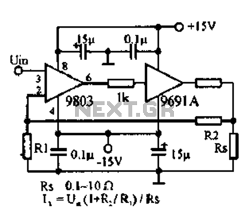
A 100W amplifier with a frequency range from DC to 500KHz features a photoelectric starting operational amplifier with high input impedance and high gain characteristics, enabling transformerless output power of 100W. The load current can reach up to 10A,...
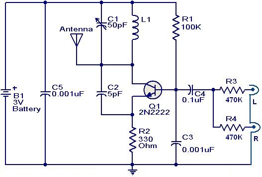
This weblog focuses on electronic circuit schematics, PCB design, DIY kits, and diagrams for electronic projects. The FM transmitter circuit utilizes the NPN transistor 2N2222. The inductor L1 and capacitor C1 generate the necessary oscillations for Q1. The collector...
The LAN tester circuit can also test cables such as telephone, coaxial, LAN, and others. This circuit uses LEDs as the main indicator device. The LAN tester circuit is designed to verify the integrity and functionality of various types of...
The metal detector circuit consists of several key components including the probe oscillator, reference oscillator, oscillation signal processor, mixing amplifier, and ammeter PA. The probe oscillator is made up of the oscillating tube VI, exploration coil L1, capacitors C1...
Warning: include(partials/cookie-banner.php): Failed to open stream: Permission denied in /var/www/html/nextgr/view-circuit.php on line 713
Warning: include(): Failed opening 'partials/cookie-banner.php' for inclusion (include_path='.:/usr/share/php') in /var/www/html/nextgr/view-circuit.php on line 713