
FM Transmitter circuit using 2N2222

The FM transmitter circuit described employs the NPN transistor 2N2222 as the core active component. The circuit is designed to operate in a compact form, suitable for integration with various audio sources such as cassette players and iPods. The inductor L1 and capacitor C1 are crucial for generating the oscillations necessary for the operation of the transmitter, which modulates audio signals onto a radio frequency.
The output stage of the circuit includes a collector capacitor (C4) and two resistors (R3 and R4) that work together to mix audio signals, ensuring that the output is in stereo format. This configuration allows for a more immersive listening experience by providing a balanced audio output to the car stereo system.
The emitter resistor (R2) plays a significant role in stabilizing the circuit. By limiting the collector current, it helps prevent overheating and excessive power consumption, thereby extending battery life. This feature is particularly beneficial in portable applications where battery efficiency is critical.
When connected to the audio output of devices like cassette players or iPods, this FM transmitter circuit enables users to broadcast their music over a short-range FM frequency. This is especially advantageous for vehicles that do not come equipped with an auxiliary input, providing a practical and cost-effective solution for enjoying personal music collections through the car's audio system. Overall, this circuit exemplifies a simple yet effective approach to integrating modern audio devices with traditional car stereos.Welcome to the weblog where we discuss about electronic circuits schematics, PCB design, diy kits and electronic projects diagrams. The FM transmitter circuit is using NPN transistor 2N2222. The L1 and C1 producess necessary oscillations Q1. The collector capacity C4, R3 and R4 resistor performs the function of the output mix theaudio to stereo pl
ayer or i-emitter resistor R2 Pod. The provides sufficient stability for circuit. It also limits the collector current increse the battery. With this circuit compact FM adapter connected to the audio output of your cassette player or i pod words, you can listen to your favorite music on the car track is stereo. This doesnot handy if your car stereo has an auxiliary circuit outlet is not to buy a short-range FM transimitter.
🔗 External reference
Related Circuits
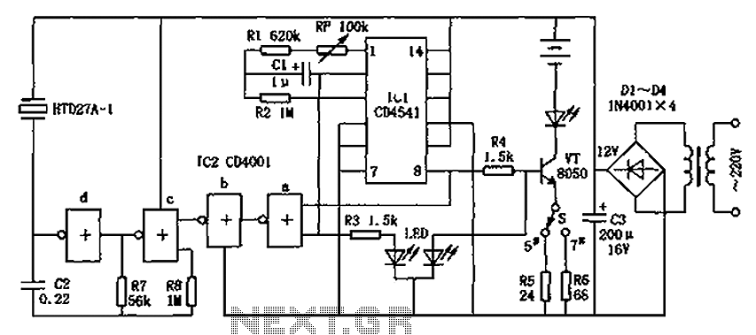
The CD4001/CD4541 nickel-cadmium battery automatic charger circuit is illustrated in the figure. This circuit is designed for charging up to seven rechargeable nickel-cadmium batteries. It features automatic charging with constant current characteristics. Once powered, the circuit activates an internal...
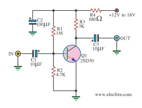
When there is a need to amplify audio signals from various sources before they reach a custom amplifier, a preamplifier (or preamp) is typically employed. This document suggests a specific circuit that is interesting due to its use of...
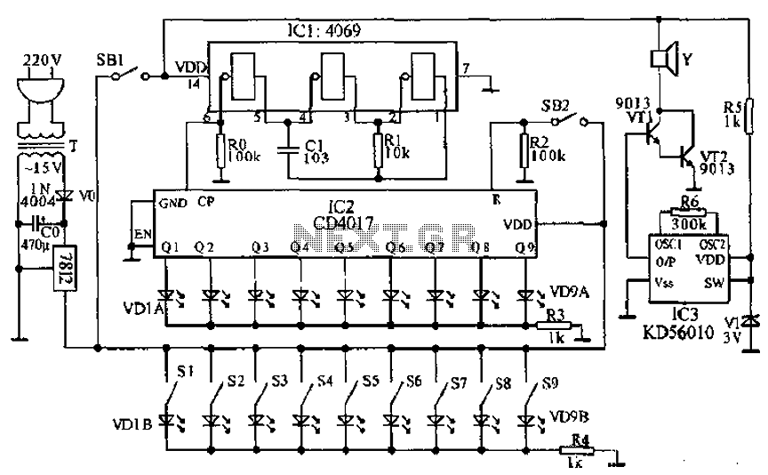
This document presents a principle circuit for electronic games. The main circuit operates in conjunction with the host through the reset button SB2, while the indicators VD1A-VD9A remain off. Prizes, for example, five, are determined by the number of...
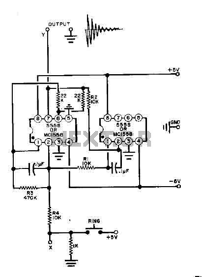
This simple bell circuit utilizes two 555 timers. The frequency is regulated by capacitors that should maintain nearly identical values for optimal performance. Fine-tuning is achieved using resistors R1 and R2. Additionally, the decay time is managed by resistor...
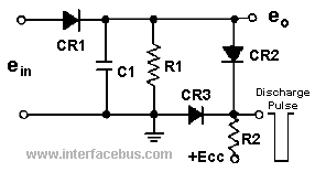
A peak detector is a circuit that detects the peak voltage of an incoming waveform. It is primarily used as an Amplitude Modulation (AM) detector, Pulse Amplitude Modulation (PAM) detector, or envelope detector. The basic form of a peak...
The tuned circuit consists of a variable capacitor and fixed air spaced coil. For the coil, wound between 10 and 20 turns of wire on an empty tube of around 1.5 inches diameter. The turns were spaced so that...