
Cable LAN Tester Circuit
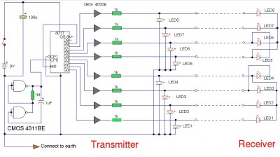
The LAN tester circuit is designed to verify the integrity and functionality of various types of cables, including telephone lines, coaxial cables, and LAN cables. The primary function of this circuit is to ensure that the connections are properly established and that there are no breaks or shorts in the wiring.
The circuit typically consists of a transmitter and a receiver module. The transmitter unit is connected to one end of the cable under test, while the receiver unit is connected to the other end. When the transmitter sends a signal through the cable, the receiver is able to detect this signal, indicating that the cable is functioning correctly.
LEDs are utilized as the main indicators in this circuit. These LEDs light up in response to the signals received, providing a visual confirmation of the cable's status. For example, a green LED may indicate a good connection, while a red LED could signify a fault or disconnection in the cable.
The circuit can be designed to accommodate multiple cable types by incorporating different testing modes. This may involve the use of switches or jumpers to select the appropriate testing configuration based on the type of cable being tested. Additionally, the circuit may feature a simple design that allows for easy assembly and troubleshooting, making it accessible for both professionals and hobbyists.
In summary, the LAN tester circuit is a versatile and essential tool for anyone involved in network installation and maintenance, ensuring that all types of cables are functioning properly and efficiently.cable LAN tester circuit can also to test cable on telephone, coaxial cable, Lan cable and other. this circuit using led for main indicator device 🔗 External reference
Related Circuits
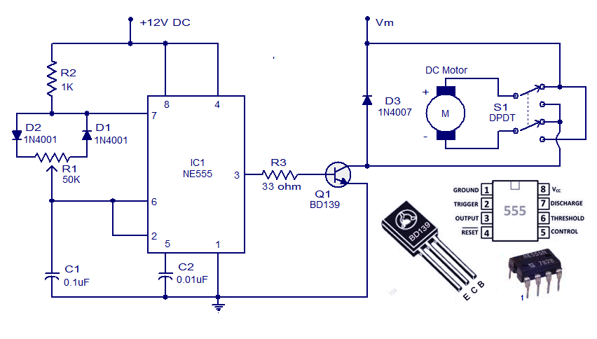
This weblog discusses electronic circuit schematics, PCB design, DIY kits, and electronic project diagrams. A simple DC motor controller circuit utilizing the NE555 timer is presented. Several DC motor speed control circuits are explored, with this being the first...
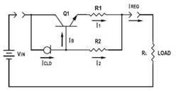
This application datasheet article includes sections that discuss the practical current booster circuit technique, which involves a conventional circuit using a Constant Current Load (CLD) and a current boosting circuit technique. It covers the analysis of the booster circuit...
The receiver is based on a basic SA612 circuit. The local oscillator (LO) for the 20-meter band operates at approximately 9 MHz, with an intermediate frequency (IF) of 5.068 MHz. The IF filter employs two crystals and has a...
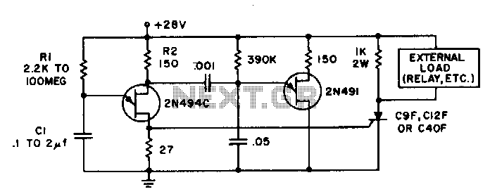
Time delays ranging from 0 milliseconds to over three minutes can be achieved with this circuit without the need for tantalum or electrolytic capacitors. The timing interval begins when power is applied to the circuit. At the conclusion of...
Powered by a solar panel, the circuit provides a 5V pure regulated DC voltage. It consists of an oscillator transistor and a regulator transistor. The solar panel charges the battery when sunlight is sufficient to generate a voltage above...
Here is the schematic diagram for a 20 Watt driver. I developed this circuit in 1985, and used it to build a lamp that found much use both as camping light and as emergency light during the then-frequent power...
Warning: include(partials/cookie-banner.php): Failed to open stream: Permission denied in /var/www/html/nextgr/view-circuit.php on line 713
Warning: include(): Failed opening 'partials/cookie-banner.php' for inclusion (include_path='.:/usr/share/php') in /var/www/html/nextgr/view-circuit.php on line 713