
Another kind of relay driver board used to utilize your old PC
To implement this project, the following steps are recommended:
1. **Component Selection**: Choose high-quality components that meet the required specifications. For the relays, ensure they can handle the necessary voltage and current ratings, especially if controlling AC devices.
2. **PCB Design**: Utilize PCB design software to create a layout that accommodates all components while maintaining adequate spacing between high-voltage and low-voltage sections. Ensure that the ground connections are solid and that the layout minimizes noise.
3. **Optocoupler Configuration**: Use the optocouplers to isolate the control signals from the high-voltage relay circuits. This is critical for protecting the LPT port and ensuring reliable operation of the relays.
4. **Testing and Validation**: After assembling the components on the PCB, conduct thorough testing to validate the functionality of each relay and the overall system. Use multimeters and oscilloscopes to check for proper voltage levels and signal integrity.
5. **Software Development**: If custom software is needed, develop it to interface with the LPT port, ensuring it can send the correct signals to activate the relays as intended. Utilize available software libraries for easier integration.
6. **Safety Precautions**: When working with high-voltage circuits, always observe safety precautions. Use insulated tools, and ensure that the power supply is disconnected when making adjustments to the circuit.
7. **Documentation**: Maintain detailed documentation of the design, component specifications, and software used. This will facilitate troubleshooting and future modifications.
By following these guidelines, the old PC can be effectively transformed into a versatile controller capable of managing various devices and applications.This article means to utilize your old PC to be come a simple controller. Many old PC like 8088 type, 8086, 80286, 80386, or even 80486 already become an obsolete systems, since they can not run many new program now a days. In fact, this system still also can be run well. Many people has let their own not used, since they have a new one (pentium t ype). Thus what for this old system now For people like us, we can use this old PC to make any experiment. Here I will stimulate you to take advantage, make a simple controller using 8 relays to make a variety uses like; turning on/off lights, turn your home stereo set, on/off you home appliance, make a timer device, make a home device alarm, etc. All application depends on your imagination. This board using 8-bits of LPT printer parallel data port (DP) to activate the relays. LPT printer parallel port also have 4-bits additional port (PC) which can be utilized too. But this is not implemented in this design, because in my opinion, 8-bits are more than enough, and beside that this size (1 byte) fit each of 8255 PPI port if we want to interface it too.
The basic is the same for all the eight channels. To protect the LPT port from damage, I use optocoupler to isolated the PC side (+5V) and relay circuit (+24V). You can change the relay voltage type to +12V or even +6V if you can find one. This type of optocoupler, PC914 can be replaced with another type like 4N series (4N22 ~ 4N28, 4N35, 4N47 ~ 4N49, etc.
). Using a common driver combination, transistor Q1 ~ Q8 (hi-power) to drive the relays. D1 ~ D8 use to protect the transistor from any transient current when the relay is in the off state. The resistor values are chosen to make transistors get full enough saturated when it is on. This common driver also can be change using IC driver like: ULN2002 ~ ULN2004 types. Each package contain 6-bits line drivers. So you need 2 of this IC, but one does not maximize. If you use PC port, than this IC can be utilized. A good alternative. Note that, for the relays, it must be stand the high voltage and current (big power) if you want to use it to drive any equiptment from the AC line. Find a good ones with a high rating output. Careful about the hi-voltage line on the PCB. Extra care must be taken in order to prevent the two different voltage lines not laying in the close distance.
I used a terminal strip to connect this hi-voltage power wire. Here I already designed the PCB for this relays driver. Not very compact, but already run well. Only data byte were used (DP port). Note that, pin 18 through 25 all together connected to ground. This PCB also included with power supply voltage regulator (+24V). Its very easy to change it to any other voltage by changed the voltage regulator only. For the data connection, as usual I used a DB-25 connector, to be easy to connected to LPT printer parallel port or for future using, when we want to connect it to any other port (like 8255-PPI port). For any reader who doesn`t have protel software, you can also printout this pdf schematic layout (90.
414 Bytes). C1 = 2200 uF/50V (elco). 1 pcs C2 = 1000 uF/25V (elco). 1 pcs D1 ~ D12 = 1N4007. 12 pcs Led1 ~ Led9 = Red Led (3 mm). 9 pcs IC1 = 7824 (voltage regulator). 1 pcs Q1 ~ Q8 = C1061 (transistor). 8 pcs OP1 ~ OP8 = PC914 (optocoupler). 8 pcs RL1 ~ RL8 = 24V relay PCB type (hi-power output, 5A/220V-AC). 8 pcs CON1 = DB-25 socket (female, PCB type, LPT connector). 1 pcs Optional CON2 = power connector. 1 pcs OUT-1 ~ OUT-8 = 2-pairs of terminal strip. 8 pcs Transformer = 15V with CT/1A or 30V-AC/1A. 1 pcs Optional on/off switch for power supply. 1 pcs Optional LPT parallel port cable (3 m). 1 pcs Optional little heatsink for voltage regulator. 1 pcs There are many `ready to use software`. Besides that you can write your own software as your purpose. But our goal now is to run our new card well. Here is a good free software I found on the electronic CD r 🔗 External reference
Related Circuits
Most individuals seeking to modify and enhance their Spectrum often focus on the keyboard as a primary area for improvement. However, a straightforward replacement requires opening the computer, which can be discouraging for two main reasons. Firstly, this action...
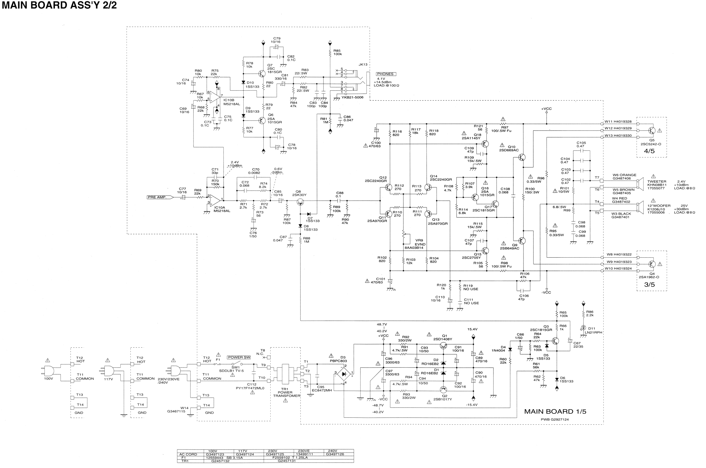
Some resistors on the circuit board of a Roland KC-300 amplifier have burned out and are so charred that their specifications cannot be determined. The resistors in question are R82, R83, R85, R92, and R93. Resistors R92 and R93...
A newer version of this circuit board is available. Rev 4 includes a faster CPU, more memory, more I/O, and an optional LCD. It is recommended to use Rev 4 for new projects. Although the older board is no...
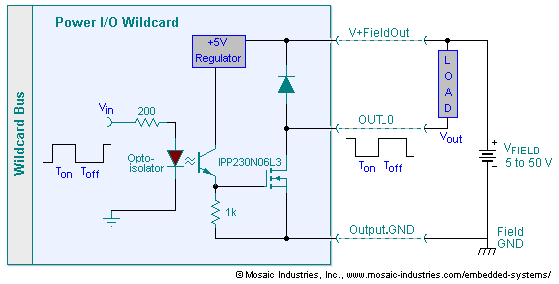
The embedded I/O board offers isolated high voltage switch inputs and eight high current, high voltage DC outputs. It utilizes optically isolated, open drain N-MOSFET transistors functioning as solid state relays (SSR) to control various resistive or inductive loads....
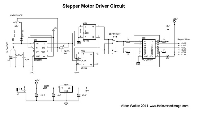
The commonly used 555 timer is configured for a variable mark/space ratio, which is essential for this application. Additionally, two D-type flip-flops (4013) are employed to provide the necessary count for the ULN2003 stepper motor driver. ULN2003 components may...
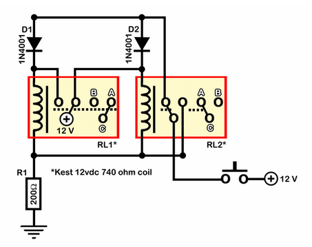
A relay circuit functions as a double-pole double-throw (DPDT) toggle, controlled by a momentary switch. The design emphasizes simplicity with minimal integration of components such as 555 timers or transistors. The circuit is depicted in an active state. Half...
Warning: include(partials/cookie-banner.php): Failed to open stream: Permission denied in /var/www/html/nextgr/view-circuit.php on line 713
Warning: include(): Failed opening 'partials/cookie-banner.php' for inclusion (include_path='.:/usr/share/php') in /var/www/html/nextgr/view-circuit.php on line 713