
Schematic Diagram Wiper Speed Control Circuits
The circuit operates as a timing and control system primarily for a wiper motor, utilizing a combination of digital and analog components to achieve its functionality. The momentary switch S1 initiates the process by generating a pulse that increments the decade counter IC2. This decade counter is essential for creating a sequence of outputs that can be selected to control the timing of the wiper motor operation.
The variable resistors VR1 through VR10 serve as adjustable timing controls, allowing for customization of the output frequency based on the user's requirements. The connection of timing resistors R4 and R5 to the astable multivibrator IC3 enables the generation of a square wave signal, which defines the operating frequency of the wiper motor. By varying the resistance values in the presets, different operational speeds can be achieved, making the system versatile for various environmental conditions.
The output from IC3 is amplified by the PNP transistor T1 (TIP32), which acts as a switch, enabling higher current flow to the final power transistor T2 (2N3055). This arrangement allows the circuit to handle the substantial current required to drive the wiper motor effectively. The choice of the 2N3055 transistor as the final power stage is significant due to its ability to handle high power loads, making it suitable for automotive applications where reliability and performance are critical.
The entire circuit is powered from the vehicle's battery, ensuring that it operates consistently during vehicle use. The monostable multivibrator IC1 is configured to provide a fixed pulse duration of approximately one second, which can help in setting a delay or a specific timing function in conjunction with the wiper motor's operation. This design effectively integrates digital logic with analog control, providing a robust solution for automotive wiper management.about-face S1 momentarily. This beating acts as a alarm beating for the decade adverse (IC2) which advances by one calculation on anniversary alternating alarm beating or the advance of about-face S1. Ten presets (VR1 through VR10), set for altered ethics by balloon and error, are acclimated at the ten outputs of IC2.
But back alone one achievemen t of IC2 is aerial at a time, alone one preset (at called output) finer comes in alternation with timing resistors R4 and R5 affiliated in the ambit of timer IC3 which functions in astable mode. As presets VR1 through VR10 are set for altered values, altered time periods (or frequencies) for astable multivibrator IC3 can be selected.
The achievement of IC3 is activated to pnp disciplinarian transistor T1 (TIP32) for active the final ability transistor T2 (2N3055) which in about-face drives the wiper motor at the called ambit speed. The ability accumulation for the wiper motor as able-bodied as the ambit is broke from the vehicle ½s array itself.
The continuance of monostable multivibrator IC1 is set for a about one additional period. 🔗 External reference
Related Circuits
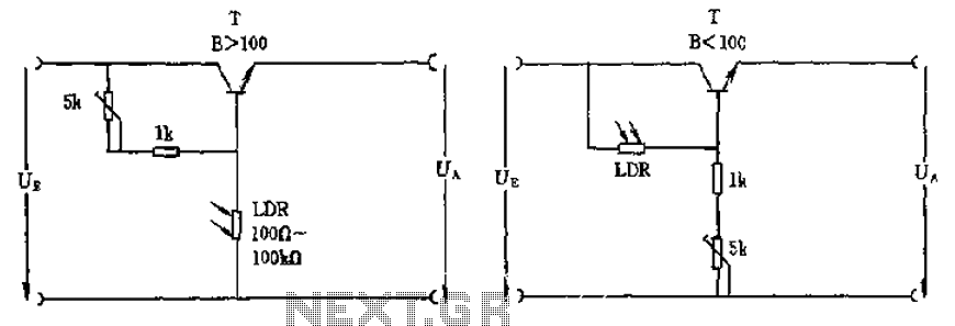
The circuit depicted involves a photoresistor (LDR) connected to a transistor, which operates at either a high or low level based on light conditions. The amplification factor of the transistor is 100, which is adequate for the application. The...
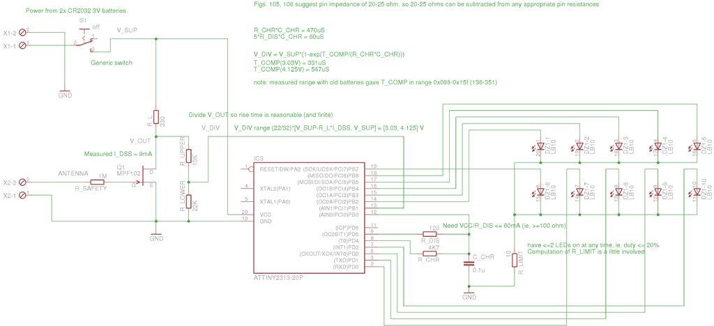
A method for measuring static electricity for a science project was sought. An old copy of "Getting Started in Electronics" by Forrest M. Mims III was referenced for guidance. To create a static electricity measurement circuit, a simple design can...
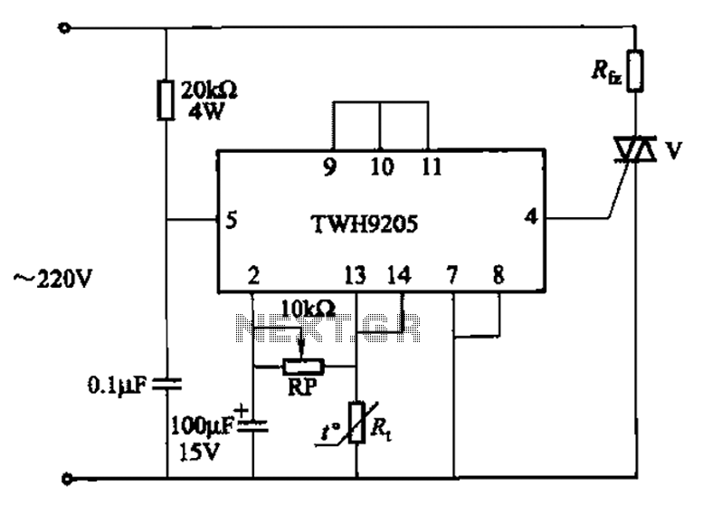
This circuit is used for temperature control in various heating equipment such as water heaters, microwave ovens, air conditioners, refrigerators, fans, and automatic fire extinguishing devices. It includes a negative temperature coefficient (NTC) thermistor as the temperature sensing element...
This circuit provides an explanation of the Phase-Locked Loop (PLL) controller unit for an FM transmitter. It is crucial for maintaining a digitally controlled and stable transmitter frequency. The core component of this unit is a PIC processor, specifically...
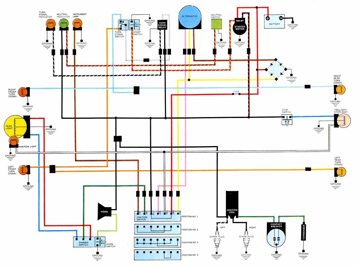
2012 Honda Odyssey Radio Wiring Diagram Manual PDF Download. The 2012 Honda Odyssey Radio Wiring Diagram Manual provides a detailed schematic of the audio system's wiring configuration for the vehicle. This manual is essential for understanding the connections and functionalities...
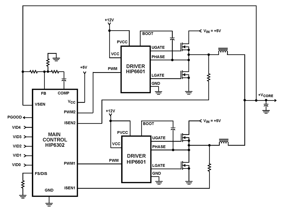
The HIP6302 Multiphase PWM control IC, along with its companion gate drivers (HIP6601, HIP6602, or HIP6603) and Intersil MOSFETs, delivers a precise voltage regulation system for advanced microprocessors. Multiphase power conversion represents a significant advancement over traditional single-phase converter...