
12 v ac dimmer

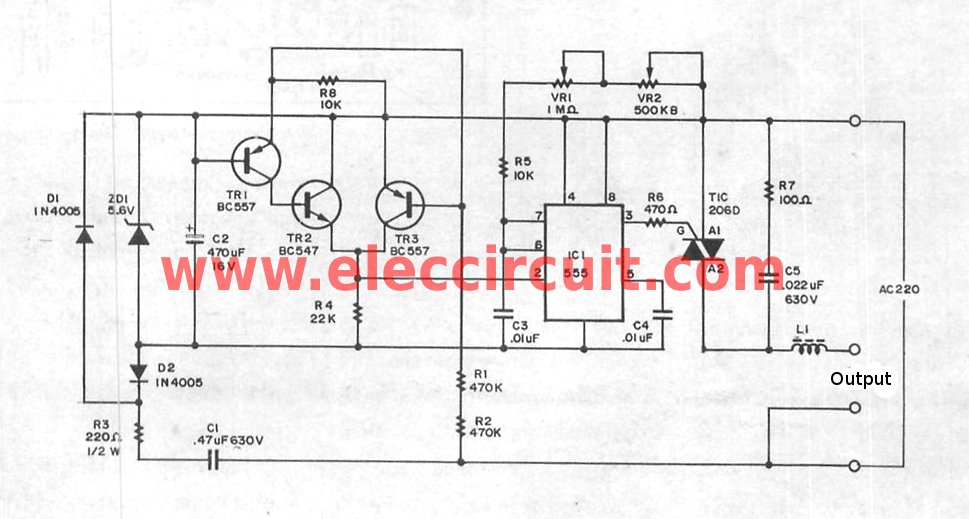
During the positive half-cycle of the sine wave, capacitor C1 charges as the voltage increases, with the time constant influenced by R1, P1, and C1. The triac T1 does not begin conducting immediately; it waits until the voltage across diode D2 reaches 4.7V, at which point the Zener diode conducts, allowing current to flow and triggering T1 and T3 into conduction. This results in a pulse at point B. The same mechanism applies during the negative half-cycle, utilizing diode D1, triac T2, and triac T4. The trigger angle is adjustable with potentiometer P1, ranging from approximately 15 degrees to 90 degrees. Capacitor C2 serves to decouple noise. Depending on the load, a heat sink may be necessary for the triac. Any suitable transistors can be employed, with the specified types serving as examples. If the dimming range is insufficient, increasing the value of P1 to 25kΩ will allow for a trigger angle increase up to 135 degrees.
The circuit operates by utilizing a triac-based dimming mechanism that is responsive to AC voltage variations. The diac-like behavior between points A and B allows for lower voltage operation, making it suitable for applications where standard diacs are ineffective. The phase-shift network consisting of R1, P1, and C1 is critical for controlling the timing of the triac's conduction, effectively modulating the power delivered to the lamp. The adjustment of the potentiometer P1 not only influences the trigger angle but also allows for fine-tuning of the dimming effect, providing versatility in lighting control.
C2 plays a significant role in stabilizing the operation of the circuit by filtering out high-frequency noise that may interfere with the functioning of the triacs. The design's flexibility in terms of component selection enables the use of various transistors, which can be chosen based on availability or specific performance characteristics required for the application. The option to incorporate a heat sink for the triac ensures reliable operation under varying load conditions, preventing overheating that could lead to circuit failure. Overall, this lamp dimmer circuit offers an effective solution for controlling light intensity in low-voltage applications, with the potential for customization to meet specific user needs.The circuit described here is derived from a conventional design for a simple lamp dimmer, as you can see if you imagine a diac connected between points A and B. The difference between this circuit and a normal diac circuit is that a diac circuit won`t work at 12 V.
This is the fault of the diac. Most diacs have a trigger voltage in the range of 30 to 40V, so they can`t work at 12 V, which means the dimmer also can`t work. The portion of the circuit between points A and B acts like a diac with a trigger voltage of approximately 5. 5 V. The network formed by R1, P1 and C1 generates a phase shift relative to the supply voltage. The diac equivalent` circuit outputs a phase-shifted trigger pulse to the triac on each positive and negative half-cycle of the sinusoidal AC voltage.
This works as follows. First consider the positive half of the sine wave. C1 charges when the voltage starts to rise, with a time constant determined by C1, R1 and P1. T1 does not start conducting right away. It waits until the voltage across D2 reaches 4. 7 V and the Zener diode starts to conduct. Then current starts to flow, driving T1 and T3 into conduction. This produces a pulse at point B. The same principle applies to the negative half of the sine wave, in this case with D1, T2 and T4 as the key players. The trigger angle can be adjusted with P1 over a range of approximately 15 degrees to 90 degrees. C2 provides a certain amount of noise decoupling. Depending on the load, the triac may need a heat sink. You can use practically any desired transistors; the types indicated here are only examples. If the circuit does not dim far enough, you can change the value of P1 to 25 k ©. This allows the trigger angle to be increased to 135 degrees. 🔗 External reference
Related Circuits
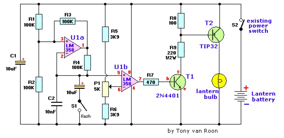
The electronic lantern control circuit enhances an existing battery-powered lantern or flashlight, or can be incorporated into a custom design, by providing high-efficiency dimming and flashing capabilities. This circuit is particularly useful in automotive applications, serving as an effective...
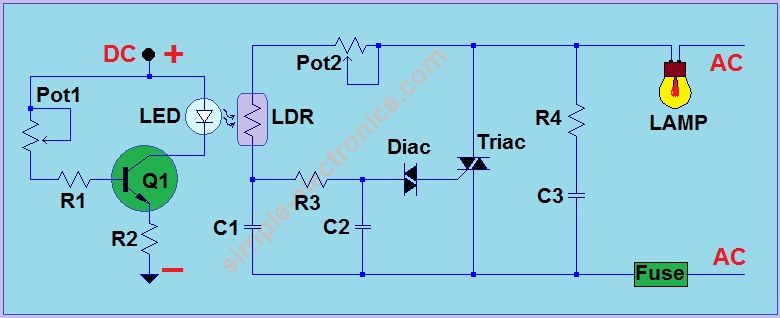
This is another AC light dimmer, with the primary distinction being that its control circuit is isolated from the AC line, making it much safer to use. The circuit can operate on both 120V and 220V AC lines. Note:...

A light timer/dimmer, similar to those found in dome lights, is desired, but guidance on how to begin the project is needed. A light timer/dimmer circuit is designed to control the brightness of a light source and to provide a...
This webpage details a highly efficient LED dimmer, which can also be referred to as a dimmable LED flashlight or a switching current source. It is an economical, single-integrated circuit (IC) solution that utilizes widely available components and is...
The super dimmer is an improved version compared to the standard dimmer currently in use. Testing its performance will provide a clearer understanding of its advantages. The super dimmer operates using advanced technology that allows for finer control over...
How to change the brightness of an LED. Are LED lights dimmable? Is it possible to adjust the brightness of LEDs? An LED is essentially a diode; when the forward voltage exceeds 0.7 volts, it begins to emit light,...