
1995 ford ranger wiring diagram
The wiring diagram for the 1995 Ford Ranger is an essential reference for understanding the electrical system of the vehicle. It provides a comprehensive overview of various components and their interconnections, which are crucial for troubleshooting and repair.
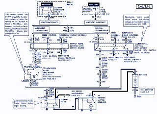
The transmission range sensor is a vital component that ensures the vehicle is in the correct gear before allowing the engine to start. It communicates with the electronic engine control unit (ECU) to confirm that the transmission is in the park or neutral position. This safety feature prevents accidental starts in gear, which could lead to accidents.
The electronic engine control system is responsible for managing engine performance and efficiency. It receives input from various sensors, including the clutch pedal position switch, which detects the position of the clutch pedal. The clutch pedal position switch jumper is used to bypass this switch during certain diagnostic procedures or when the switch is faulty.
Speed control is integrated into the electronic engine control system, allowing for cruise control functionality. This system maintains a set speed without the driver needing to keep their foot on the accelerator pedal, enhancing driving comfort on long trips.
The automatic transmission components within the wiring diagram include connections for the starter interrupt relay. This relay prevents the starter motor from engaging unless the transmission is in the proper position. The relay box houses various relays, including those for the starter motor, ensuring that power is distributed correctly during engine starting.
The starter motor is activated by the starter relay, which receives a signal from the ignition switch. The starter motor solenoid is also part of this system, acting as a switch that engages the starter motor when the ignition is turned on.
For manual transmission vehicles, the wiring diagram includes specific connections that differ from those of automatic transmissions, ensuring proper functionality of all components.
The battery is a crucial element in the electrical system, providing the necessary power to start the engine and operate various electrical components. The I/P fuse panel contains fuses that protect different circuits within the vehicle, ensuring that electrical faults do not cause damage to the system.
Overall, the wiring diagram for the 1995 Ford Ranger serves as a detailed guide for technicians and engineers, facilitating the maintenance and repair of the vehicle's electrical system. Understanding the relationships between these components is essential for effective troubleshooting and ensuring the vehicle operates safely and efficiently.The Part of 1995 Ford Ranger Wiring Diagram: transmission range sensor, electronic engine control, clutch pedal position switch jumper, electronic engine control, speed control, automatic transmission, starter interupt relay, rela box, starter motor during engine starting, starter relay, manual transmission, electronic engine control, battery, sta rter motor solenoid, switch jumper, I/P fuse panel. 🔗 External reference
Related Circuits
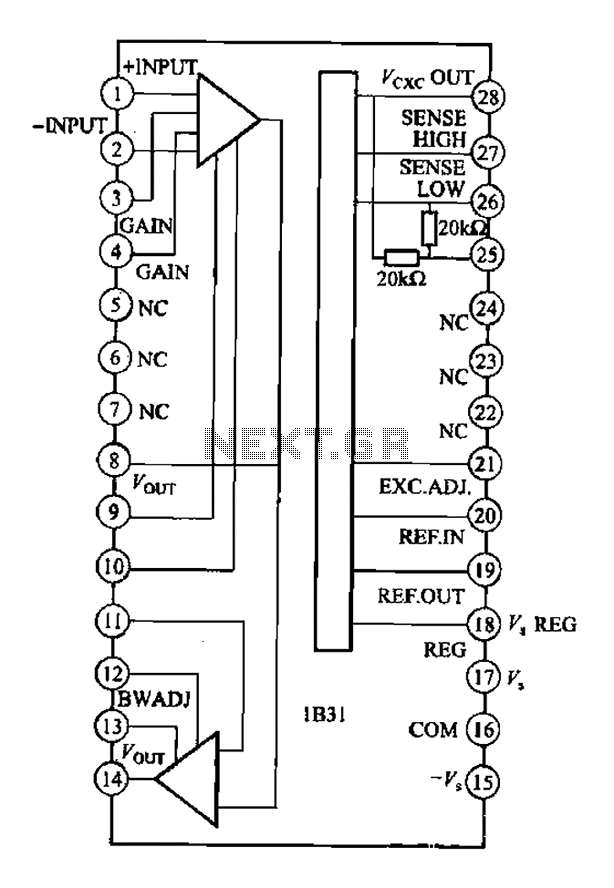
The Analog Devices 1831 is designed for strain gauge signal conditioning applications. It features an internal low drift input of 0.25V with a gain of 1000, exhibiting excellent linearity with a maximum deviation of 0.005%. The IC operates with...
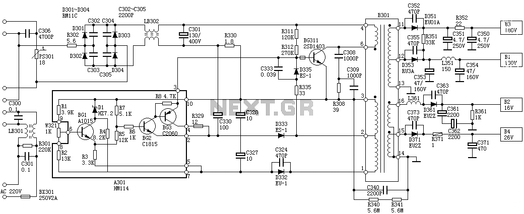
Oscillation: The positive terminal voltage of C310 is approximately 300V. The resistors R311 and R312 are connected to the switch BG311 at the B pole, while the B301 winding via the switching transformer (4) and (6) is connected to...
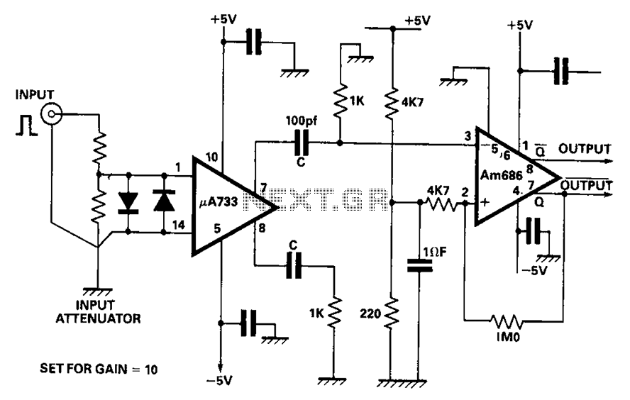
A video amplifier output arrives at a differentiation stage before the Schottky comparator. The typical propagation delay is reduced to 10 ns. The output pulse width is determined by the capacitance value, where C is 100 pF, resulting in...
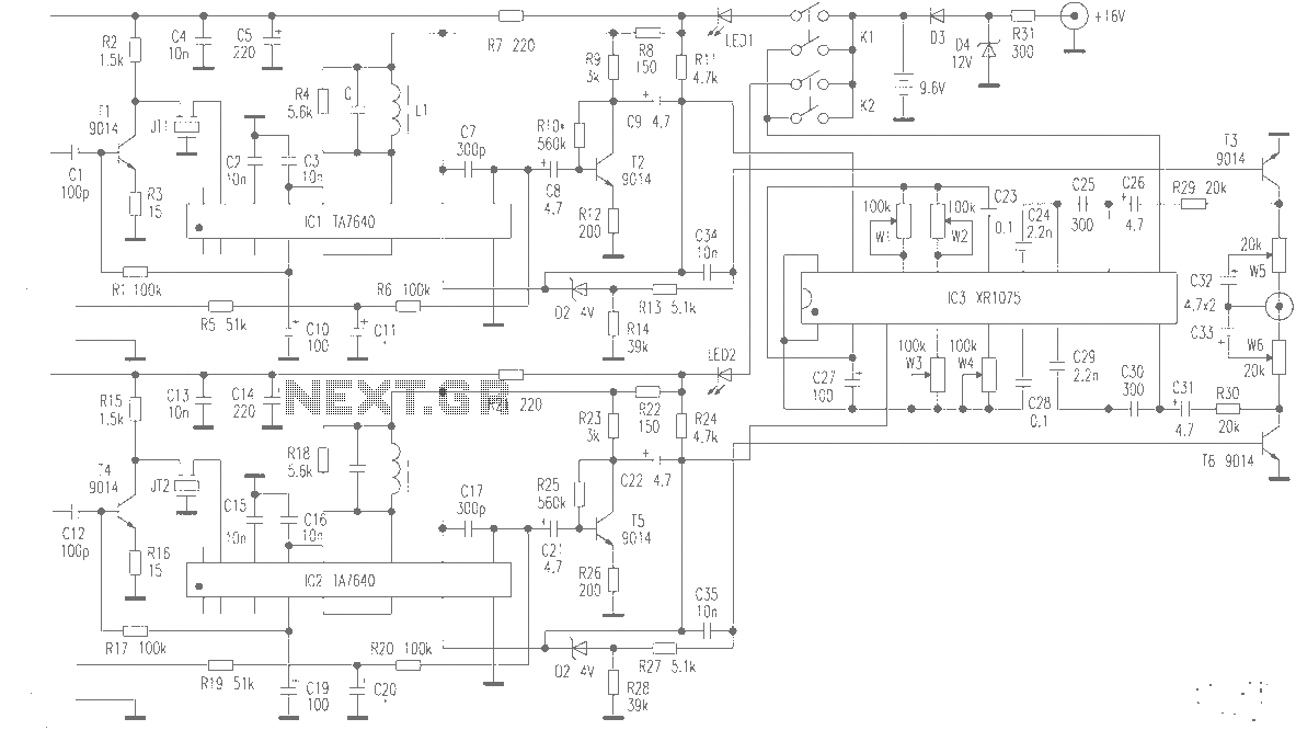
The production of high-quality wireless microphones is a common aspiration among enthusiasts, but achieving a high-performance receiver is challenging. This project explores the use of salvaged FM radio cassette players to enhance an XR1075 audio processor, leading to the...
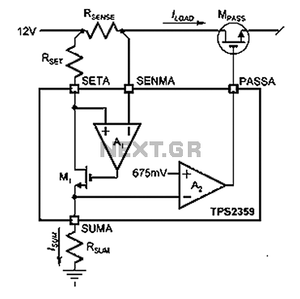
Amplifier A1 utilizes the voltage across the sense resistor sensors to monitor the load current ILOAD. The power management channel employs a similar circuit, with the distinction of integrating resistors RSENSE and RSET. Amplifier A1 is configured to measure the...
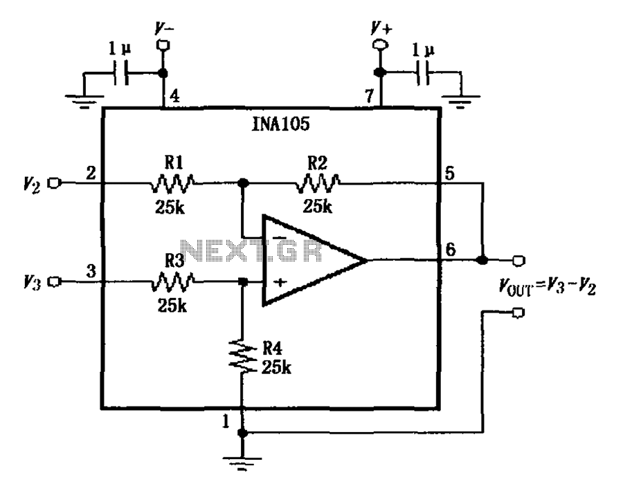
The power supply terminal should utilize a 1 µF chip capacitor filter, positioned as close as possible to the chip's supply pin. The signal is generated by the input pins 2 and 3. The source resistance of the signal...