
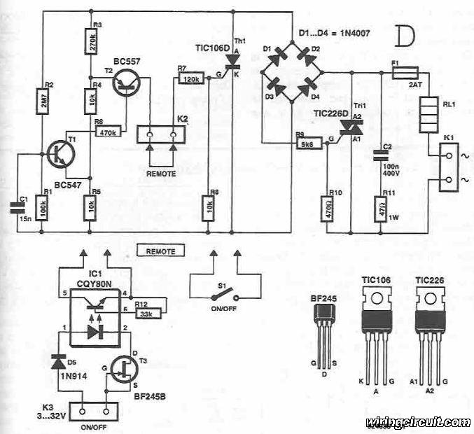
4011 IC For Protection Surge Electronic CIrcuit Diagram

The 4011 IC is a quad 2-input NAND gate, which can be employed in various electronic applications, including surge protection circuits. In this specific application, the circuit utilizes the NAND gates to create a delay mechanism that protects connected appliances from voltage spikes or surges.
The basic operation of the circuit involves the use of the 4011 IC to monitor the input voltage levels. When a surge is detected, the circuit will momentarily disconnect the output to prevent damage to the appliances. The delay feature is crucial, as it allows for transient surges to dissipate before re-engaging the output.
The schematic typically includes the 4011 IC connected to a power supply, input surge detection components (such as diodes or varistors), and output control elements (like relays or transistors) to manage the power to the connected appliances. Resistors and capacitors are also included to set the timing for the delay and filter out noise.
This circuit is particularly beneficial in environments where electrical surges are common, providing an essential layer of protection for sensitive electronic devices. The design should ensure that all components are rated appropriately for the expected voltage and current levels to maintain reliability and safety.This circuit shows about 4011 IC For Protection Surge Electronic CIrcuit Diagram. Features: used to delay other appliances connected to the output .. 🔗 External reference
Related Circuits
This circuit diagram illustrates the design of a straightforward AC voltage converter that transforms 240V AC power into 110V AC. The circuit can effectively be utilized to power electrical devices that necessitate a supply voltage of 110V. The AC voltage...
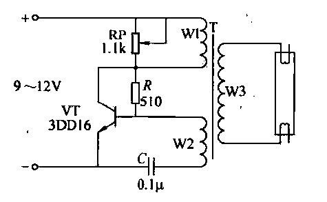
This circuit is designed for the ignition of a direct current (DC) fluorescent lamp rated between 6 to 8 watts. It utilizes a common pole-blocking oscillator that consists of a transistor (VT) and is induced by the secondary side...
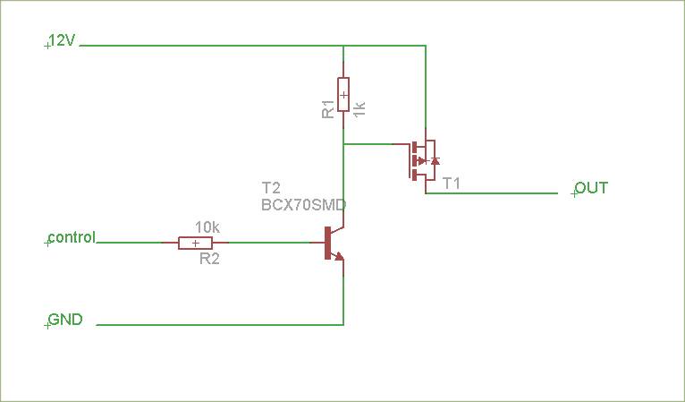
The schematic is attached. Suggestions for improvements are requested, particularly for adding reverse polarity connection protection. The logic level inputs (5 V) are designed to control two output voltages (12 V) using P-channel MOSFETs. The P-channel MOSFETs are ON...
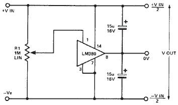
A simple split power supply circuit can be designed using the schematic diagram based on the LM380 audio power integrated circuit (IC). The output voltage regulation is dependent on the circuit feeding the LM380. The power dissipation is approximately...
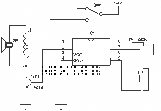
The alarm circuit operates as follows: When the power switch SW1 is turned on, the alarm system becomes active. If a magnet is brought close to the spring, the magnetic field attracts the spring, causing the dynamic and static...
This circuit is a metal detector designed to detect large metallic objects at depths ranging from 2 to 3 meters, depending on the size of the object and the type of soil. The construction is straightforward, making it accessible...