
Ultra High Sensitivity Metal Detector Circuit
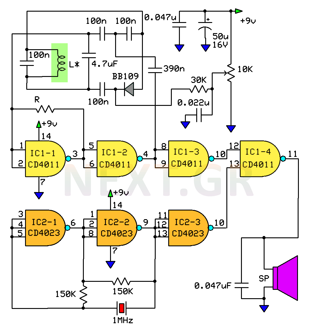
The circuit employs the IC1, which is the CD4011, and the IC2, the CD4023, both of which are logic integrated circuits. The reference generator is implemented using two logic elements from the IC2, with its frequency stabilized by a 1 MHz quartz crystal (X). The variable frequency generator is constructed using the first two elements of the IC1, where the oscillating circuit consists of the search coil (L), capacitors, and a varicap. A 10K potentiometer is used for tuning to a frequency of 100 kHz, which sets the necessary voltage to the varicap (VD1).
Signal logic elements IC1-3 and IC2-3 function as buffer amplifiers, while the signal mixer is IC1-4. A high-resistance phone capsule serves as the speaker, and capacitor C10 acts as a shunt capacitor for high-frequency signals from the mixer. The metal detector circuit is powered by a 9V DC battery or can utilize six AA batteries for extended operation. Capacitors C8 and C9 serve as filters. The construction of the search coil requires precision; it should be wound on a plastic tube with an external diameter of 20 cm, containing 100 turns of 0.3 mm wire. After winding, the coil should be wrapped in aluminum foil to create an electrostatic shield, reducing capacitance effects between the coil and the ground. Care must be taken to ensure there is no electrical contact between the winding wire and the foil, which should be protected from physical damage with insulating tape. The coil should be secured in a waterproof casing to prevent damage and moisture exposure.
The coil diameter can vary from 20 cm; however, a smaller coil increases sensitivity while narrowing the searching area for hidden metallic objects, and vice versa for larger coils. When the search coil is positioned close to the ground, the detector should be adjusted using the potentiometer until the sound in the speaker is minimal. The detector is then ready for use; if a metallic object is within the coil's range, the sound will increase in volume.
An update indicates that a resistor with a value of 150KΩ is required.This circuit is a metal detector capable of detecting large metallic objects. at a depth of 2m to 3m. It depends on the size of the object, and often on the type of soil. Construction is very easy to implement even for a beginner. The necessary components are easy to find everywhere. This detector has the ability to detect a gold coin of 20mm and a thickness of 1.5mm and a depth of 90cm. The two present frequencies are the one that is generated by the circuit and the one that is returning for comparison.
By placing the coil near a metallic object the returning frequency is changed. Those two frequencies are the subject of comparison by our circuit. At modern metal detectors, the reference generator operates at a frequency that has different magnitude from that which appears in the field of the search coil.
How the circuit works
The circuit uses the IC1 which is the CD4011 and the IC2, the CD4023, both of these are logic ICs. The reference generator is implemented in two logic elements of the integrated circuit IC2. Its frequency is stabilized and is determined by the quartz crystal X which is 1MHz. The generator with a variable frequency is made on the first two elements of the IC1. The oscillating circuit here is formed by the search coil L, the capacitors and the varicap. The potentiometer 10K is for tuning to a frequency of 100kHz, this actually sets the required voltage to the varicap VD1.
The circuit use the signal logic elements IC1-3 and IC2-3 as buffer amplifiers and the signal mixer is the IC1-4.
The speaker should be a high resistance phone capsule. And the capacitor C10 is used as a shunt capacitor for the high frequency coming from the mixer.
The metal detector circuit is powered by a 9V DC battery or you can use 6 AA batteries for much longer working times. The capacitors C8 and C9 work as a filter. The search coil requires special precision and attention in its construction.
It should be wound on a plastic tube with an external diameter of 20cm.
The coil should contain 100 turns of 0.3mm wire. When the winding of the coil is completed, it should be wrapped in aluminum foil to create an electrostatic shield (this will reduce the effect of the capacitance between the coil and ground). It is important not to allow electrical contact between the winding wire and the foil. The aluminum foil itself should be protected from physical damage, so it should be wounded well with an insulating tape.
Then you should secure the coil in a water proof hard casing, to protect it from damaging it and to get wet.
The diameter of the coil can be different than 20cm. But the smaller the coil, the more sensitive the circuit becomes, but the area of searching for hidden metal objects narrows.
When the diameter of the coil is increased, the same effect is reversed.
Having located the search coil close to the ground surface, adjust the detector with the potentiometer. And so that in the speaker capsule the sound is almost none. Now you are ready to use it and search. If a metallic object will be in the range of the coil the sound will get loud.
Update: Missing resistor value R = 150KΩ.
Related Circuits
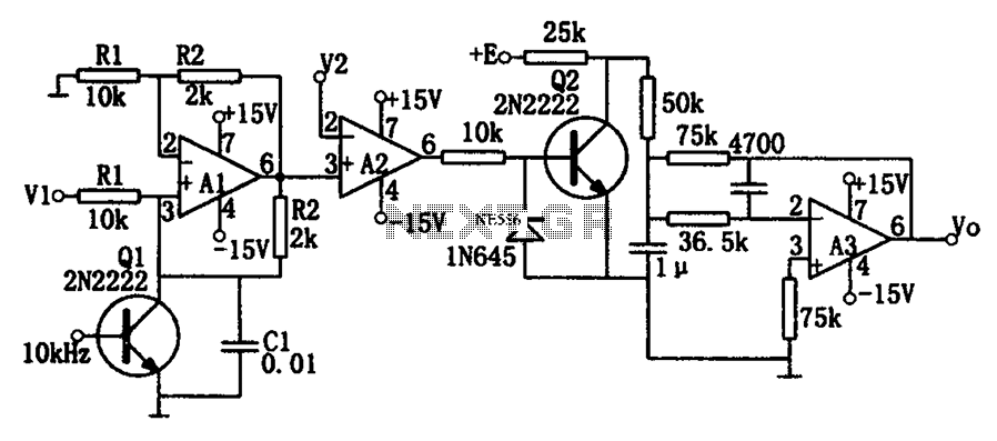
As illustrated in the dividing circuit diagram, A1 consists of a voltage-controlled current source, A2 functions as a voltage comparator, and A3 is configured as an active low-pass filter. When the time constant R1C1 is equal to the clock...
The Panasonic transducers are no longer available, but the design remains interesting as an example. J1 connects to the RCX. D1 to D4 create a bridge rectifier to obtain local power from the RCX, which is stored on C7...
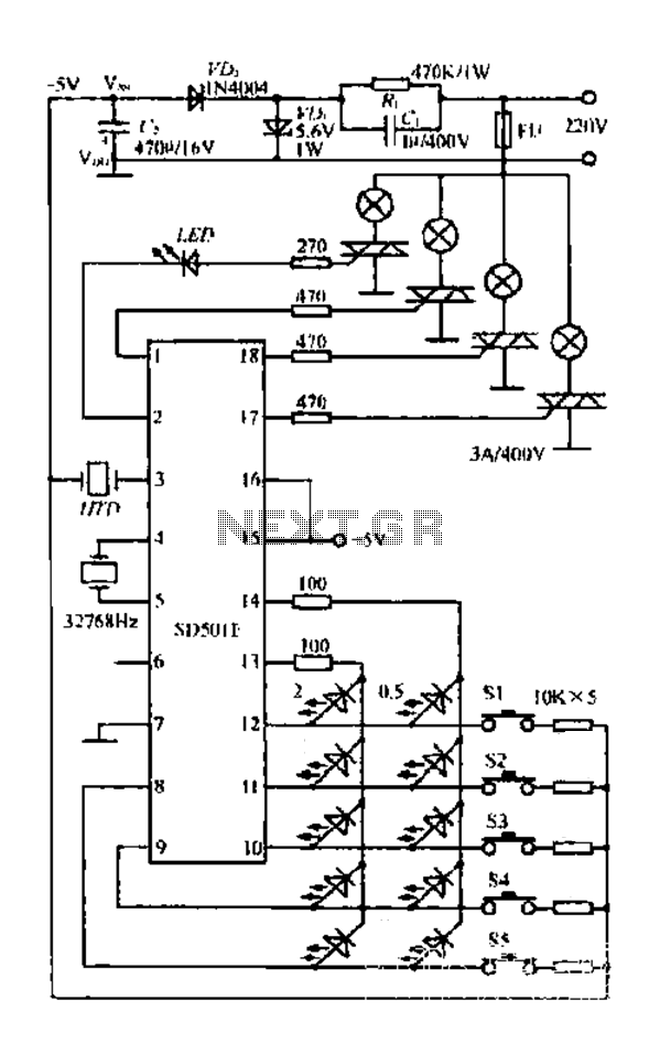
The FIG SD501E is a J tie fan integrated circuit (IC) characterized by progressive timing and three operational modes: strong, medium, and weak. It features three types of output settings and includes an electrical swing mechanism. The device is...
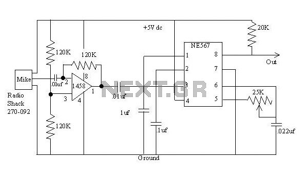
The detector is a bit more complex. It amplifies a microphone and sends the resulting signal to an NE567 tone decoder. The amplifier is half of a 1458 opamp. The two 120K resistors attached to pin 3 keep the...
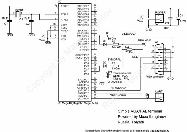
To prevent image distortion when receiving data via UART for VGA, it is advisable to conduct data exchange with the terminal approximately 300-600 microseconds after the vertical synchronization (VSYNC) signal. In a VGA system, the synchronization signals are crucial for...
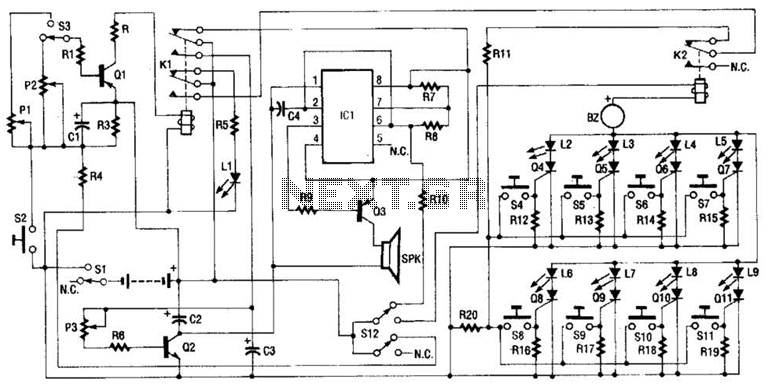
Up to eight players each have their own answer button to press, corresponding to the four Red Team and four Green Team LEDs on the master control board. As soon as the first contestant who thinks they know the...